Multifocal spectacle lens

a spectacle lens and multi-focal technology, applied in the field of multi-focal spectacle lenses, can solve the problems of front surface of the lens, and limited power at the lower area of the lens, so as to achieve sufficient optical performance and improve workability

Inactive Publication Date: 2006-04-04
SEIKO OPTICAL PROD TRADING AS SEIKO OPTICAL PROD +1
View PDF8 Cites 1 Cited by
  • Summary
  • Abstract
  • Description
  • Claims
  • Application Information

AI Technical Summary

Benefits of technology

The present invention provides a multifocal spectacle lens that has sufficient optical performance to meet a customer's specification and is configured to improve workability. The lens has a front surface and a back surface, each formed as a multifocal surface and a progressive-power surface, with different surface power distributions. The average surface power of the upper and lower areas of the front surface may be greater than the average surface power of the upper and lower areas of the back surface. The lens may also have a distance portion for distance vision and intermediate or near vision. The front surface may have a segment for bifocal vision. The back surface may have astigmatic power to correct astigmatism. The method includes producing semifinished lens blanks and selecting one of them based on the customer's specification. The back surface of the selected lens blank is then processed accordingly. The processing may include adjusting the positional relationship between the distribution of power of the front and back surfaces, or changing the length of the progressive-power portion of the lens.

Problems solved by technology

This means that the varieties of the front surface of the lens (e.g., distribution of power on the lens surface, the number of combinations of addition power at the upper area of the lens and addition power at the lower area of the lens, the length of a progressive-power portion) are limited.
Therefore, it is very difficult to stockpile semifinished spectacle lens blanks which cover all types of the customer's specifications.
However, in this case, swinging and distortion of an image peculiar to mulitifocal spectacle lenses becomes greater in comparison with a multifocal spectacle lens having a progressive-power surface on its back surface.
This makes the process for producing the lens difficult.

Method used


Image

  • Multifocal spectacle lens
  • Multifocal spectacle lens
  • Multifocal spectacle lens

Examples


first embodiment

[0083]FIG. 1 is a sectional view of a multifocal spectacle lens L1 according to a first embodiment of the present invention. As shown in FIG. 1, the lens L1 has a front surface 11 (an object side) and a back surface 12 (an eye side). The lens L1 is designed to correct middle distance vision and near vision.

[0084]FIG. 2A shows a contour line of surface astigmatism of the front surface 11. FIG. 2B shows a contour line of average surface power of the front surface 11.

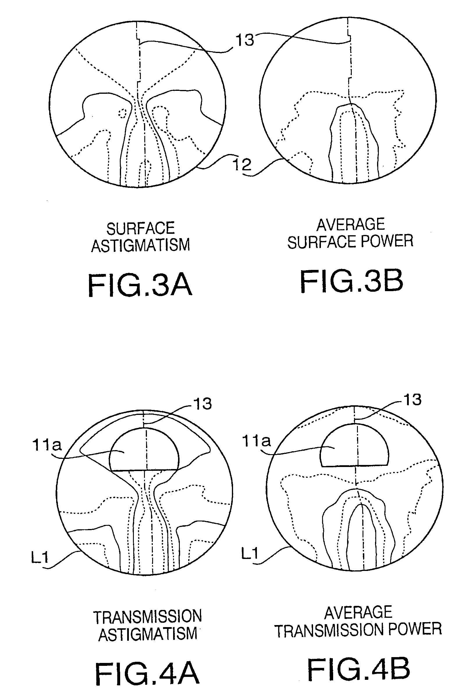
[0085]FIG. 3A shows contour lines of surface astigmatism of the back surface 12. FIG. 3B shows contour lines of average surface power of the back surface 12.

[0086]FIG. 4A shows contour lines as to astigmatism of the lens L1 (hereafter, referred to as “transmission astigmatism”). FIG. 4B shows contour lines as to average refractive power of the lens L1 (hereafter, referred to as “average transmission power”).

[0087]In each of FIGS. 2A–4B, an interval between adjacent contour lines corresponds to 0.5 (unit: D), and a chain li...

second embodiment

[0094]FIG. 8 shows a sectional view of a multifocal spectacle lens L2 according to a second embodiment of the present invention. The lens L2 is designed to correct myopia and astigmatism. A shown in FIG. 8, the lens L2 has a front surface 21 and a back surface 22.

[0095]FIG. 9A shows a contour line of surface astigmatism of the front surface 21. FIG. 9B shows a contour line of average surface power of the front surface 21.

[0096]FIG. 10A shows contour lines of surface astigmatism of the back surface 22. FIG. 10B shows contour lines of average surface power of the back surface 22.

[0097]FIG. 11A shows contour lines as to transmission astigmatism of the lens L2. FIG. 11B shows contour lines as to average transmission power of the lens L2.

[0098]In each of FIGS. 9A–11B, an interval between adjacent contour lines corresponds to 0.5 (unit: D), and a chain line 23 represents a fixation line.

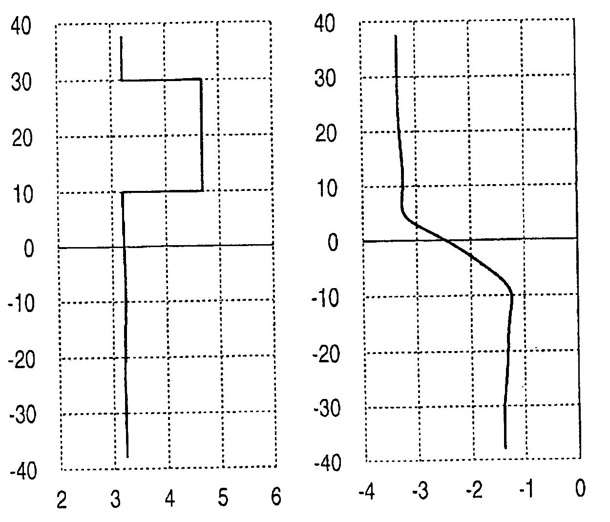
[0099]FIG. 12 is a graph showing the average surface power of the front surface 21 along the fixation l...

third embodiment

[0105]FIG. 15 shows a sectional view of a multifocal spectacle lens L3 according to a third embodiment of the present invention. As shown in FIG. 15, the lens L3 has a front surface 31 (an object side) and a back surface 32 (an eye side). The lens L3 is designed to have power to correct hyperopia.

[0106]FIG. 16A shows a contour line of surface astigmatism of the front surface 31. FIG. 16B shows a contour line of average surface power of the front surface 31.

[0107]FIG. 17A shows contour lines of surface astigmatism of the back surface 32. FIG. 17B shows contour lines of average surface power of the back surface 32.

[0108]FIG. 18A shows contour lines as to transmission astigmatism of the lens L3. FIG. 18B shows contour lines as to average transmission power of the lens L3.

[0109]In each of FIGS. 16A–18B, an interval between adjacent contour lines corresponds to 0.5 (unit: D), and a chain line 33 represents a fixation line.

[0110]FIG. 19 is a graph showing the average surface power of the ...


PUM


Abstract

There is provided a multifocal spectacle lens having a front surface and a back surface each of the front surface and the back surface is formed as a multifocal surface or a progressive-power surface, distributions of surface power of the front surface and the back surface being different from each other.

Description

BACKGROUND OF THE INVENTION[0001]The present invention relates to a multifocal spectacle lens and producing methods thereof.[0002]Conventionally, multifocal spectacle lenses have been widely used to compensate for age-related decrease in amplitude of accommodation of eye. The multifocal spectacle lens includes a lens having a discontinuously changing refractive power such as a bifocal lens and a trifocal lens, and a progressive-power spectacle lens having a continuously changing refractive power.[0003]In general, an upper area of a spectacle lens is used for distance vision and a lower area of the spectacle lens is used for near vision. Therefore, the conventional multifocal spectacle lens has a distance portion having dioptric power for distance vision at an upper area of the lens and a near portion having a dioptic power for near vision at a lower area of the lens.[0004]However, in a particular case, it is required that the upper area of the spectacle lens is used for near vision ...

Claims


Application Information

Patent Timeline
Patent Type & Authority Patents(United States)
IPC IPC(8): G02C7/06G02C7/02
CPCG02C7/06G02C7/068G02C7/061
Inventor SHIRAYANAGI, MORIYASU
Owner SEIKO OPTICAL PROD TRADING AS SEIKO OPTICAL PROD
Why Eureka
Try Eureka