
Methods, apparatuses and systems for blind mating arrays of multi-optical fiber connector modules

a technology of optical fiber connector modules and blind mating arrays, applied in the field of optical communication, can solve problems such as signal degradation, unacceptable bit error rate (ber), and insufficient precision of optical alignment along the optical pathway to prevent unacceptable optical loss

Active Publication Date: 2015-08-13
AVAGO TECH INT SALES PTE LTD
View PDF1 Cites 6 Cited by
  • Summary
  • Abstract
  • Description
  • Claims
  • Application Information

AI Technical Summary

Benefits of technology

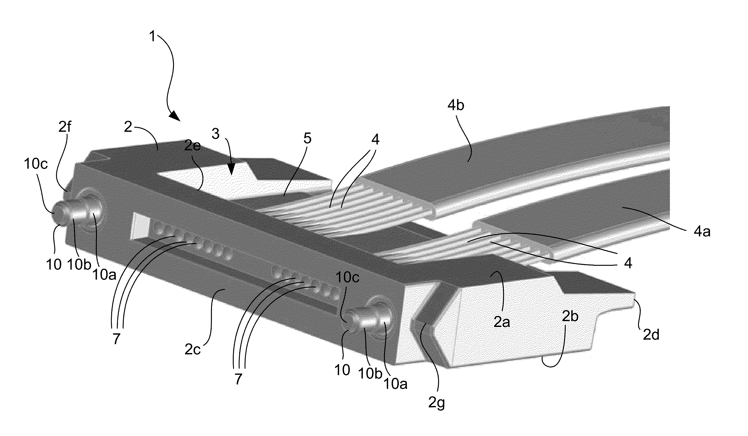
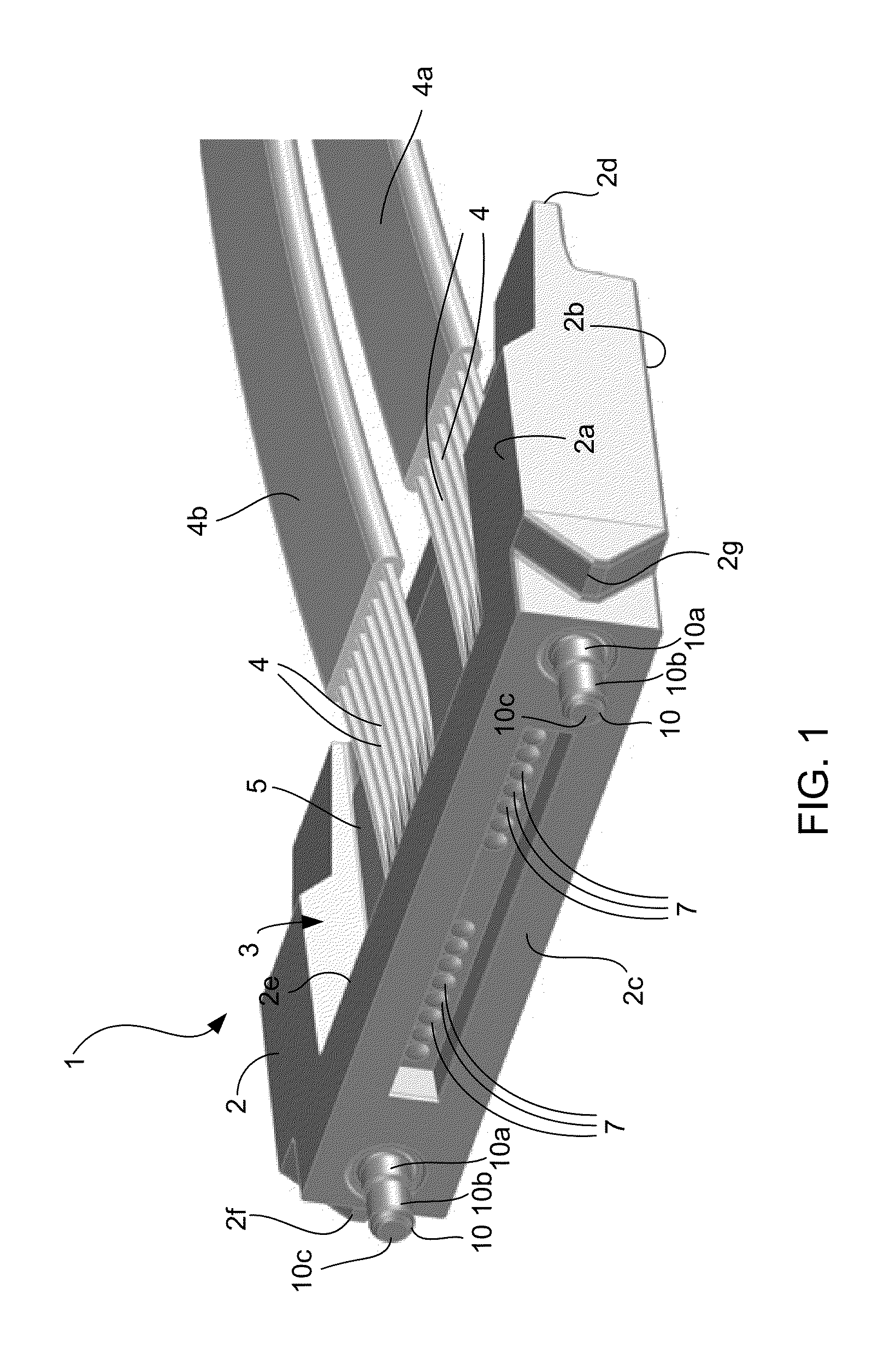
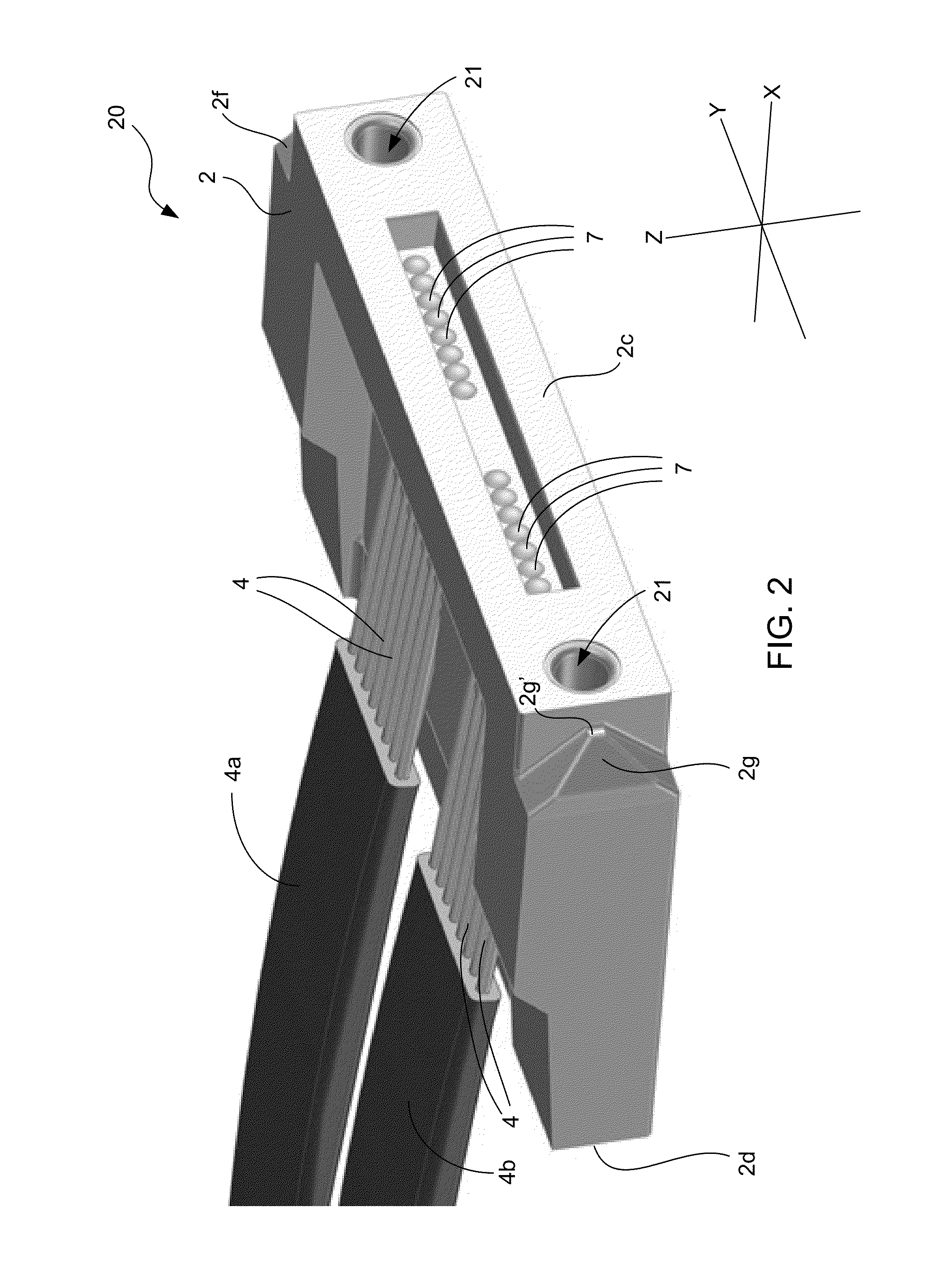
The invention is about a system and method for mating optical fiber connector modules. The system includes a guide system, a first holder, and a first 1-by-N array of connector modules. The first holder has limited freedom of movement relative to the guide system. The first holder has a mating feature that matches with a mating feature of the first holder. The first connector modules have passive fine alignment features that align with passive fine alignment features of the second multi-optical fiber connector modules. The system also includes a second holder and a second 1-by-N array of connector modules. The second holder has a mating feature that matches with the mating feature of the first holder. The second connector modules have passive fine alignment features that align with the passive fine alignment features of the first connector modules. The full mating of the connector modules aligns their optical pathways. The technical effect of the invention is to provide a reliable and precise method for mating optical fiber connector modules.

Problems solved by technology

Unacceptable optical losses lead to signal degradation, which can lead to an unacceptable bit error rate (BER).
Otherwise, the optical alignment along the optical pathways will not have sufficient precision to prevent unacceptable optical losses from occurring.
However, manufacturing the modules with very tight mechanical tolerances increases manufacturing costs, which increases the overall costs of the modules.
In addition, the need to achieve very tight mechanical tolerances can lead to a decrease in yield for the modules, which also increases the overall costs of the modules.
While such passive alignment features generally work well for their intended purposes, they are not suitable for simultaneous blind mating of multiple connector modules with multiple respective mating modules or receptacles.
Making these interconnections can be a difficult and time-consuming task.

Method used


Image

  • Methods, apparatuses and systems for blind mating arrays of multi-optical fiber connector modules
  • Methods, apparatuses and systems for blind mating arrays of multi-optical fiber connector modules
  • Methods, apparatuses and systems for blind mating arrays of multi-optical fiber connector modules

Examples


Embodiment Construction

[0031]Embodiments of the invention include apparatuses, systems and methods that enable N female multi-optical fiber connector modules disposed on a first structure to be simultaneously blind mated with N male multi-optical fiber connector modules disposed on a second structure, where N is a positive integer that is equal to or greater than two. Enabling the male and female multi-optical fiber connector modules to blind mate with one another obviates the need to individually interconnect the modules with optical cables, as is the common practice. On one of the structures, a first holder is mounted that includes a 1×N array of female sockets. On each female socket of the array, a respective male or female multi-optical fiber connector module is mounted. Similarly, on the other structure, a second holder is mounted that includes a 1×N array of male sockets. On each male socket of the array, a respective male or female multi-optical fiber connector module is mounted.

[0032]The first and...


PUM


Abstract

Apparatuses, systems and methods are provided that enable a first array of multi-optical fiber connector modules disposed on a first structure to be blindly mated with a second array of multi-optical fiber connector modules disposed on a second structure. The arrays of modules are mounted on respective holders. One of the holders is mounted on the first structure and the other holder is mounted on the second structure. Engagement of the first and second structures with one another results in mating features of the holders being brought within a predetermined allowable misalignment tolerance of one another to ensure that the holders fully mate with one another. Mating of the holders with one another brings mating features of the connector modules of the arrays into a predetermined allowable misalignment tolerance of one another to ensure that full mating of the respective connector modules of the arrays occurs.

Description

TECHNICAL FIELD OF THE INVENTION[0001]The invention relates to optical communications. More particularly, the invention relates to methods and systems for blind mating arrays of multi-optical fiber connector modules.BACKGROUND OF THE INVENTION[0002]Multi-optical fiber connector modules are used to mechanically couple the ends of a plurality of optical fibers to a parallel optical communications module that has a plurality of optical channels. The parallel optical communications module may be a parallel optical transceiver module having both transmit and receive optical channels, a parallel optical transmitter module having only transmit optical channels, or a parallel optical receiver module having only receive optical channels. A typical multi-optical fiber connector module includes an optics system that couples light between the ends of the optical fibers and respective optoelectronic devices that are contained within the parallel optical communications module. For transmit optica...

Claims


Application Information

Patent Timeline
Patent Type & Authority Applications(United States)
IPC IPC(8): G02B6/38
CPCG02B6/3883G02B6/3885G02B6/3895
Inventor MCCOLLOCH, LAURENCE R.
Owner AVAGO TECH INT SALES PTE LTD
Learn More