Dual Flow Septic Vent
- Summary
- Abstract
- Description
- Claims
- Application Information
AI Technical Summary
Benefits of technology
Problems solved by technology
Method used
Image
Examples
Embodiment Construction
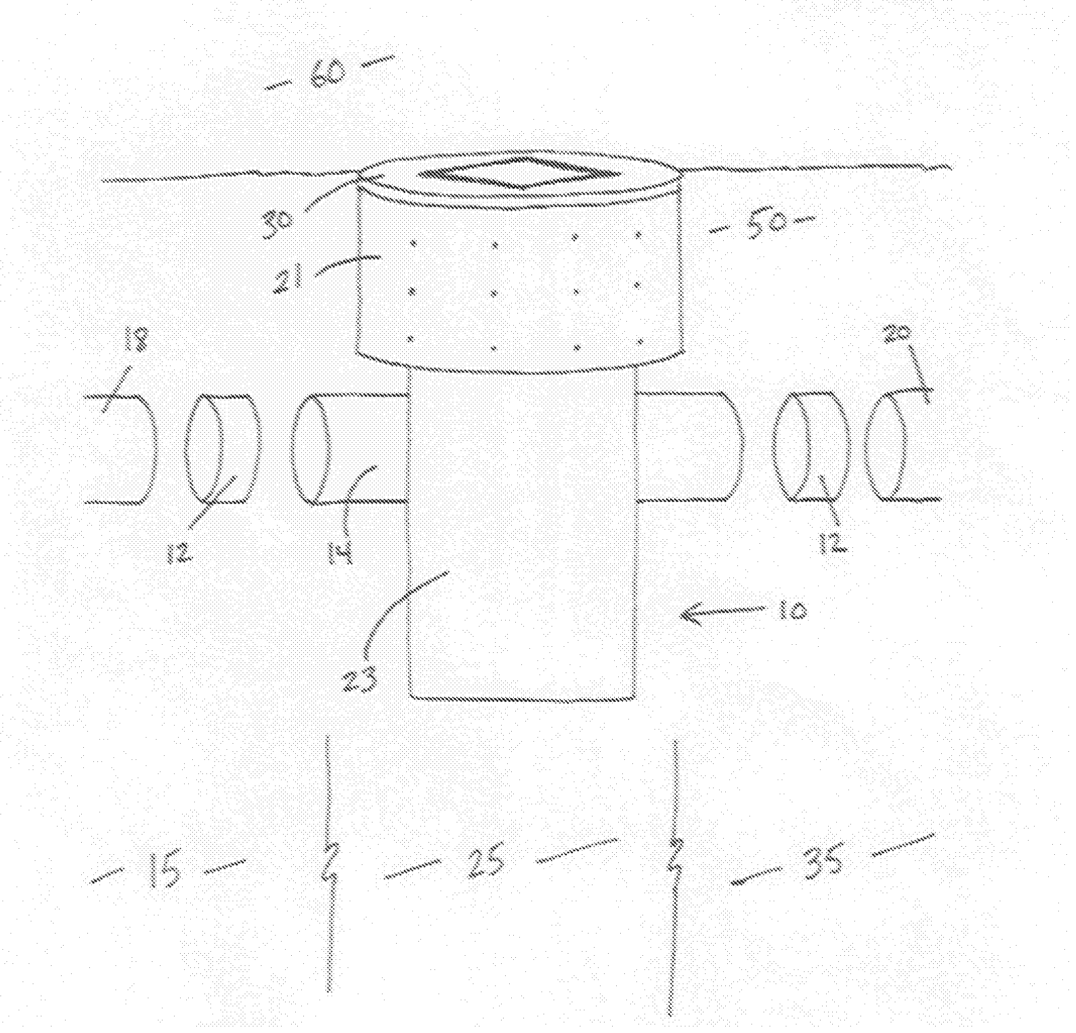
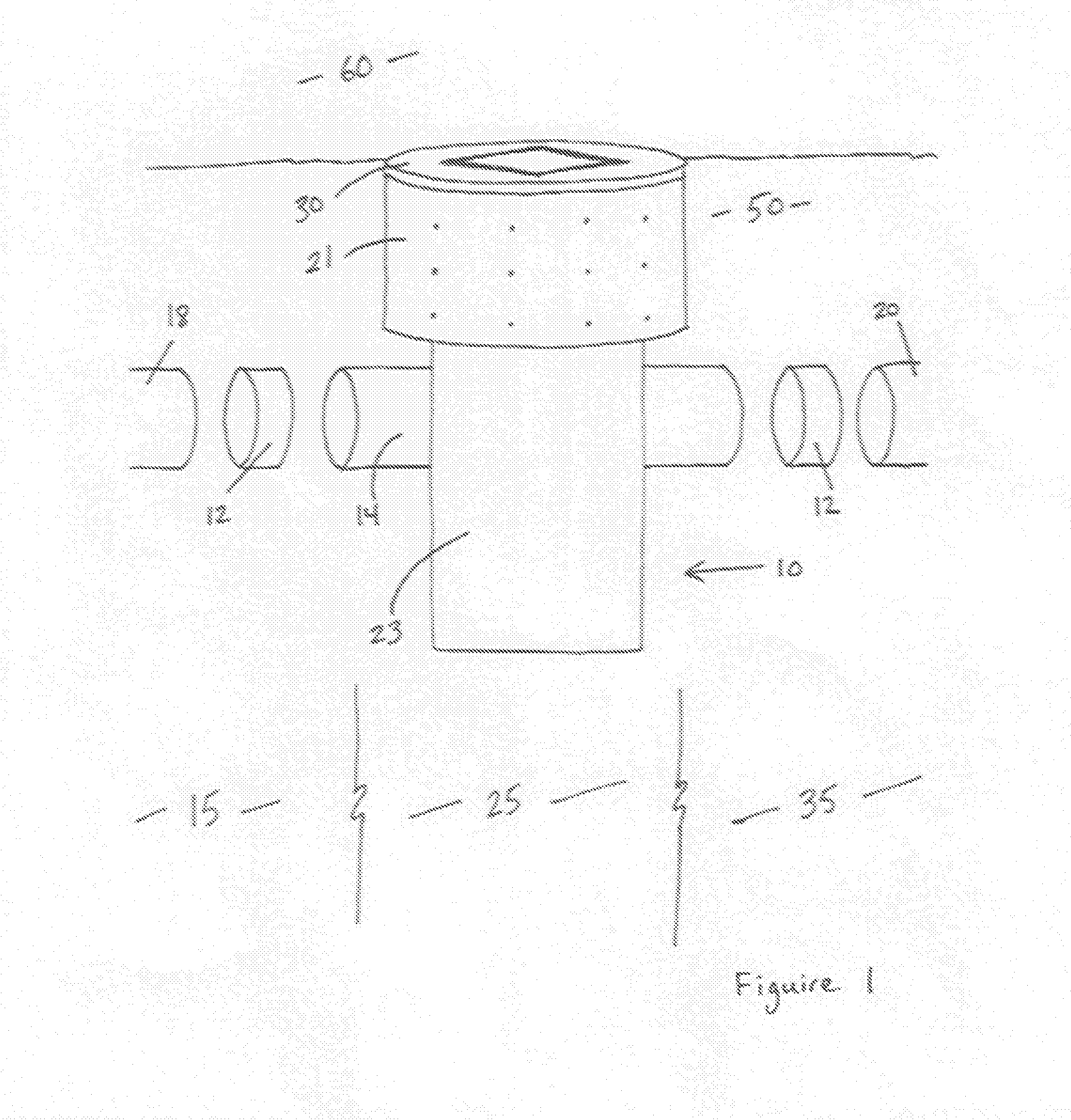
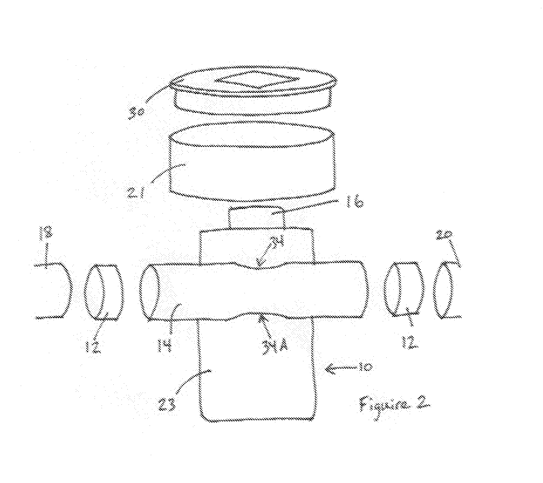
[0013]With further reference to the drawings, the dual flow septic vent of the present invention are shown therein and indicated generally by the numeral 10. As will be appreciated from subsequent portions of this disclosure, septic vent 10 is designed to be located or positioned at the transition zone 25 following an anaerobic environment 15 such as a septic tank 18 or a pressure manifold 18 and preceding an aerobic environment 35 such as a distribution device 20 that disperses effluent flow to a final treatment area. Activated carbon filter access cover 30 is designed to be placed at grade level 60 and septic vent 10 extends into the soil media 50. Flow channel 14 is aligned with an approved connection 12 such that effluent flow is directed through the flow channel 14 and across the dosing chamber 23 for final dispersion to the distribution device 20.
[0014]Septic vent 10 includes a surrounding sidewall structure 21. Extending between the sidewall structure 21 is a free access 16 t...
PUM
| Property | Measurement | Unit |
|---|---|---|
| Flow rate | aaaaa | aaaaa |
| Surface area | aaaaa | aaaaa |
| Environmental properties | aaaaa | aaaaa |
Abstract
Description
Claims
Application Information
 - R&D
- Intellectual Property
- Life Sciences
- Materials
- Tech Scout
- Unparalleled Data Quality
- Higher Quality Content
- 60% Fewer Hallucinations
Browse by: Latest US Patents, China's latest patents, Technical Efficacy Thesaurus, Application Domain, Technology Topic, Popular Technical Reports.
© 2025 PatSnap. All rights reserved.Legal|Privacy policy|Modern Slavery Act Transparency Statement|Sitemap|About US| Contact US: help@patsnap.com


