Brake light drive control device

a control device and brake light technology, applied in signalling/lighting devices, vehicle components, optical signalling, etc., can solve problems such as overcurrent flowing through the semiconductor device circuit, and achieve the effects of reducing the number of repeated on/off operations, and reducing the stress on the semiconductor device of the semiconductor device circui

Inactive Publication Date: 2015-08-13
YAZAKI CORP
View PDF0 Cites 3 Cited by
  • Summary
  • Abstract
  • Description
  • Claims
  • Application Information

AI Technical Summary

Benefits of technology

[0027]According to the brake light drive control device of the first aspect of the present invention, in the case where the overcurrent is caused in the semiconductor device circuit configured to output the pulsed driving electric power to the brake light, even when the brake pedal is repeatedly operated, the controller stops outputting the drive signal after repeatedly outputting the drive signal in accordance with the operation of the brake pedal at the predetermined times, so as to decrease the number of repeated ON/OFF operation of the semiconductor device circuit.
[0028]According to the brake light drive control device of the first aspect of the present invention, in the case where the overcurren...

Problems solved by technology

If a short circuit is caused between the semiconductor device circuit and the brake lights because of a par...

Method used


Image

  • Brake light drive control device
  • Brake light drive control device
  • Brake light drive control device

Examples


Embodiment Construction

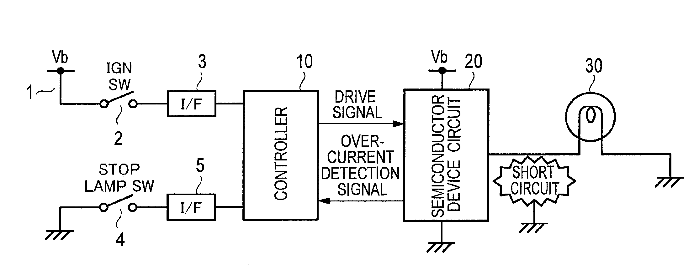
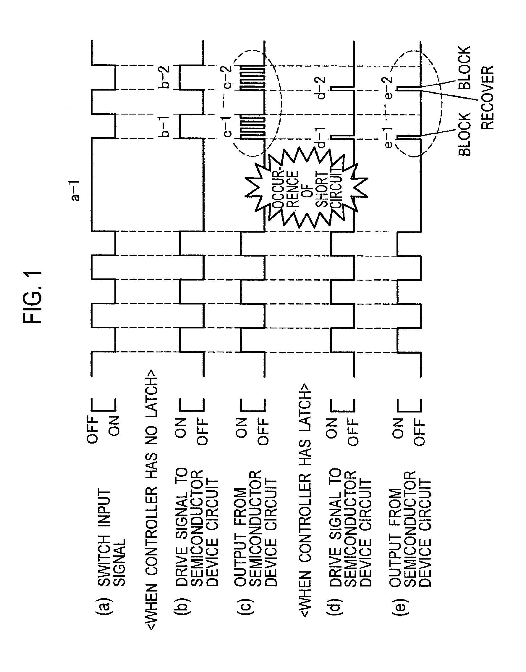
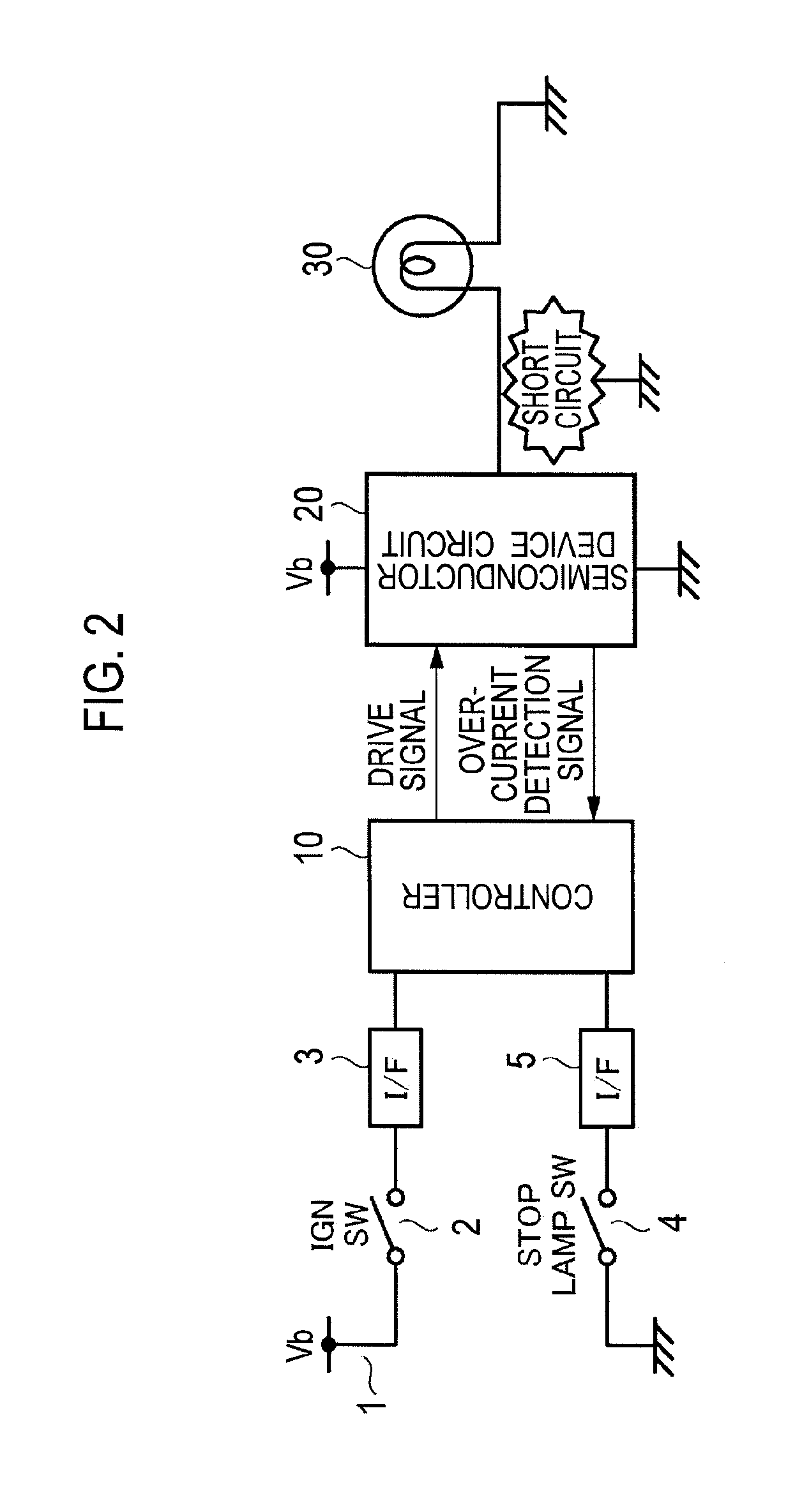
[0032]Hereinafter, a brake light drive control device according to an embodiment will be explained with reference to FIG. 2. Note that a fundamental control operation by the brake light drive control device according to the embodiment is applied to a case in which a controller includes a latch, as illustrated by Charts (d) and (e) of FIG. 1. Here, “latch” means that, when the controller receives an overcurrent detection signal, a state that a switching device of a semiconductor device circuit is turned off is kept every time a switch input signal is detected, as in the case described above.

[0033]As illustrated in FIG. 2, the brake light drive control device includes a controller 10 and a semiconductor device circuit 20.

[0034]The controller 10 is connected, on the input side, with an ignition switch (IGN SW) 2 connected to a battery 1, and with an interface (I / F) 3 which outputs, to the controller 10, a signal indicating that the ignition switch 2 is turned on.

[0035]Here, the ignitio...


PUM


Abstract

In a brake light drive control device, in a case where an overcurrent is caused in a semiconductor device circuit (20) which outputs pulsed driving electric power to a brake light, even when a brake pedal is repeatedly operated, a controller (10) stops outputting a drive signal after repeatedly outputting the drive signal in accordance with the operation of the brake pedal at predetermined times. Accordingly, the number of repeated ON/OFF operation of a switching device as a semiconductor device of the semiconductor device circuit (20) decreases.

Description

TECHNICAL FIELD[0001]The present invention relates to a brake light drive control device used for implementing drive control of brake lights including brake lamps and a stop lamp installed in a vehicle and particularly used for protecting a semiconductor device circuit for driving the brake lights.BACKGROUND ART[0002]A vehicle is provided, on the rear side thereof, with brake lamps as brake lights arranged on both right and left sides. The vehicle is sometimes further provided with a stop lamp as brake light located substantially in the middle of the rear side, in addition to the brake lamps. These brake lights are lighted by a brake light drive control device when brake pedals are used.[0003]The brake light drive control device includes a semiconductor device circuit which outputs driving electric power to the brake lights, and a controller which controls the operation of the semiconductor device circuit. Once a key is turned to a position at which an engine starts, an ignition swi...

Claims


Application Information

Patent Timeline
IPC IPC(8): B60Q1/44
CPCB60Q1/441B60Q1/44B60Q11/00
Inventor KONDOU, TATSUMI
Owner YAZAKI CORP
Why Eureka
Try Eureka