
Generator load control

a technology for generators and load, applied in the direction of generator load control, load forecast in ac network, ac network voltage adjustment, etc., can solve the problems of rig and generator automatically shutting down, large power consumption of electric equipment, etc., and achieve the effect of minimal efficient load rating

Active Publication Date: 2015-08-06
NABORS DRILLING TECH USA INC
View PDF13 Cites 9 Cited by
  • Summary
  • Abstract
  • Description
  • Claims
  • Application Information

AI Technical Summary

Benefits of technology

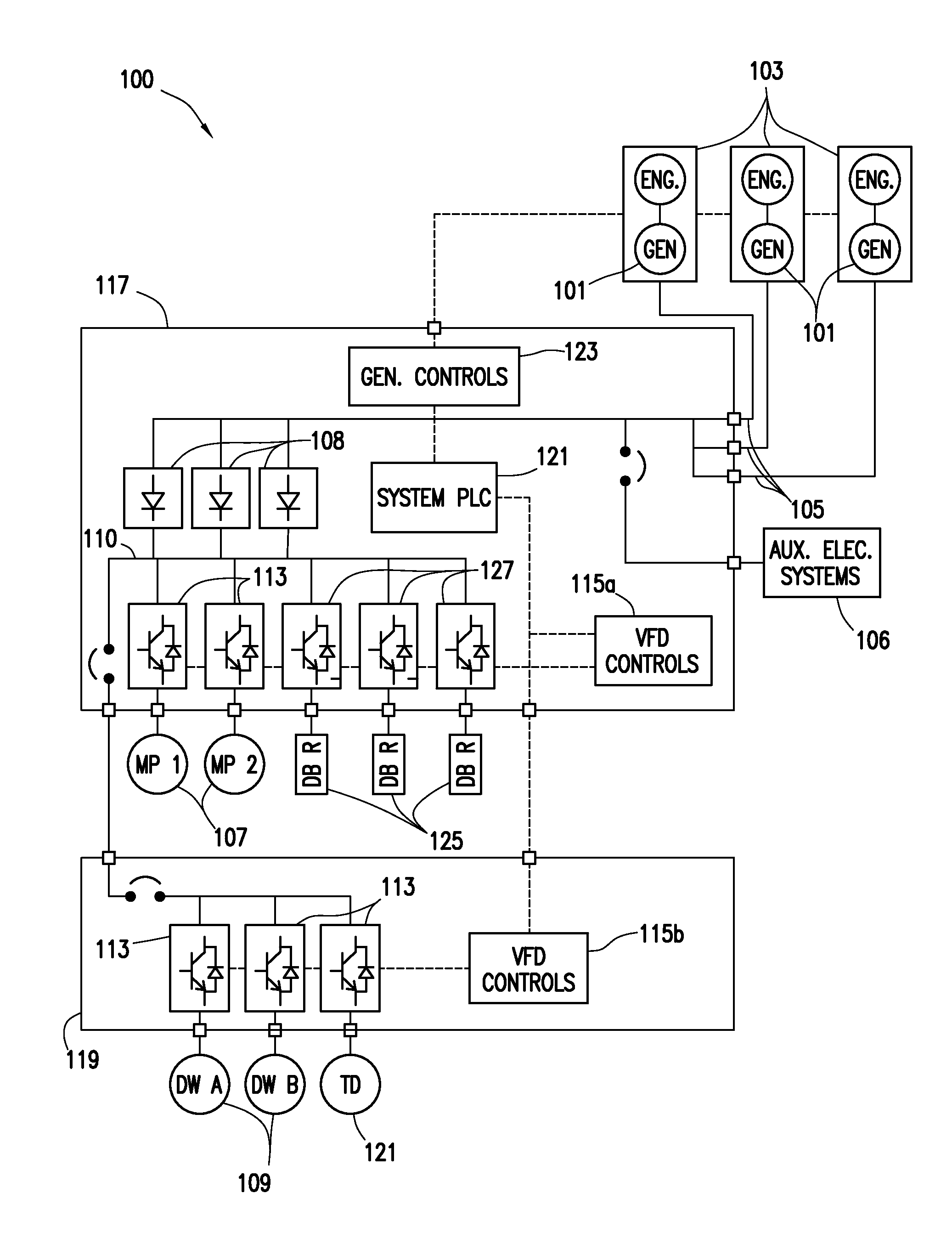
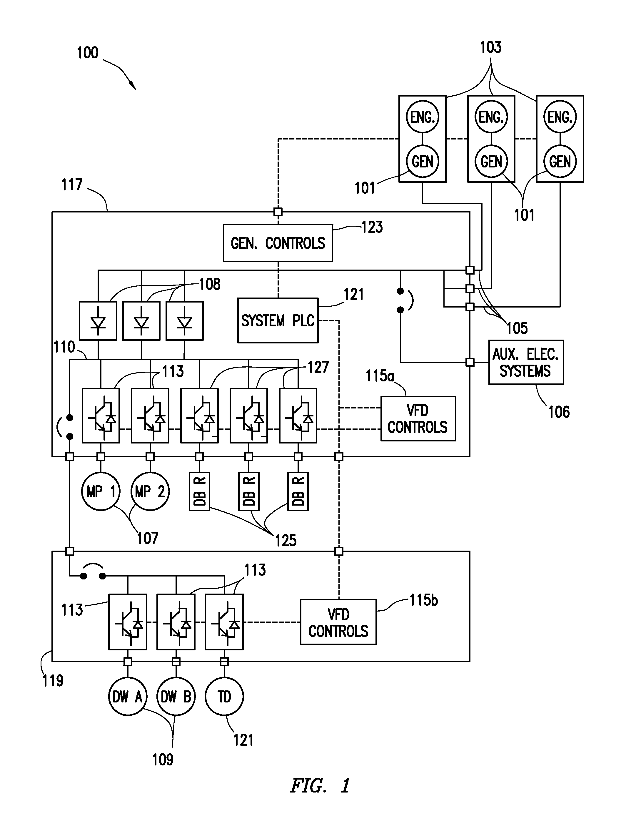
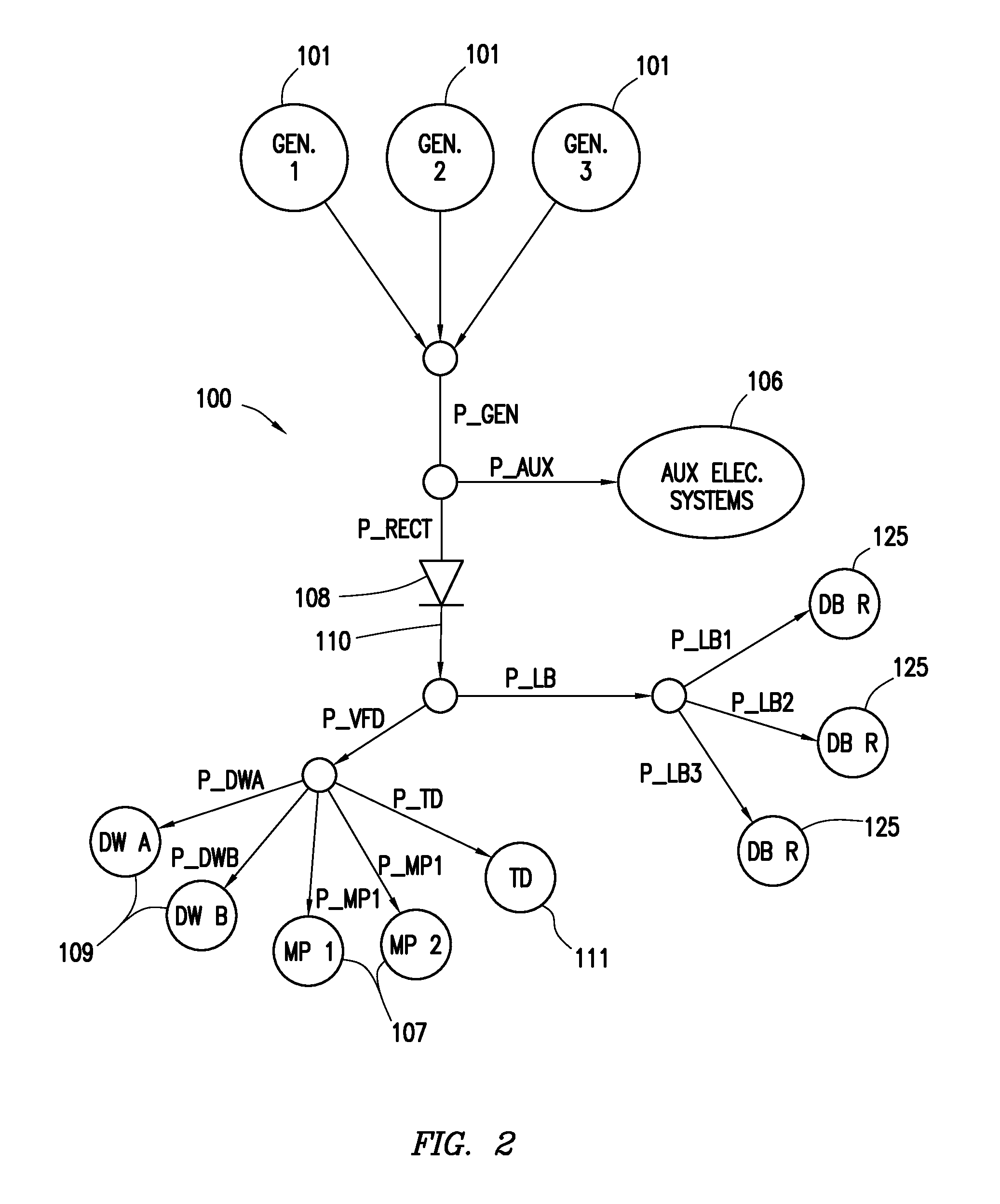
The present disclosure describes a power system for running electrically driven devices using a power load. The power system includes a generator with a minimum efficient load rating, a load bank that provides a passive load on the generator, and a controller that engages the load bank to activate the passive load. The method involves calculating the minimum total load of the generators and the total power demand of the electrically driven devices. The controller engages the load bank to provide the passive load to the generators, which is equal to the demand. The technical effect is that the power system is designed to efficiently use the generators and reduce energy waste.

Problems solved by technology

Electrical equipment, including drawworks, mud pumps, top drives, rotary tables, etc. may consume large amounts of power when in use.
Additionally, a rapid decrease in electric load may cause a power spike which may cause the rig and generator to automatically shut down.

Method used


Image

  • Generator load control
  • Generator load control
  • Generator load control

Examples


Embodiment Construction

[0011]It is to be understood that the following disclosure provides many different embodiments, or examples, for implementing different features of various embodiments. Specific examples of components and arrangements are described below to simplify the present disclosure. These are, of course, merely examples and are not intended to be limiting. In addition, the present disclosure may repeat reference numerals and / or letters in the various examples. This repetition is for the purpose of simplicity and clarity and does not in itself dictate a relationship between the various embodiments and / or configurations discussed.

[0012]In some embodiments, a drilling rig power system is powered by one or more electric generators. The electric generators power electrical equipment on the drilling rig, as well as other electrical systems. Electrical equipment may include, for example and without limitation, drawworks, mud pumps, top drives, rotary tables, power tongs, pipe spinners, hydraulic pum...


PUM


Abstract

A power system for an electrical system with highly fluctuating loads is powered by one or more power sources that are slow to react to load changes. The power sources are connected to electrical equipment used on the drill rig which provide active load to the generators. One or more load banks may be positioned to provide passive load to the generators to maintain generally constant generator load, while allowing for instant access to power as active load increases. Generators may be run at 100% capacity, a maximum efficient capacity, or at a high enough level to allow for a sufficiently rapid increase in power output. At least one parameter of a drilling operation may be utilized to anticipate load demand changes.

Description

CROSS REFERENCE TO RELATED APPLICATIONS[0001]This application is a non-provisional application which claims priority from U.S. provisional application No. 61 / 935,472 filed Feb. 4, 2014 and U.S. provisional application No. 62 / 010,652 filed Jun. 11, 2014.TECHNICAL FIELD / FIELD OF THE DISCLOSURE[0002]The present disclosure relates generally to electric power transmission from a power source to a time-variant load, and specifically to powering electrical systems with highly fluctuating loads from one or more power sources that are slow to react to load changes.BACKGROUND OF THE DISCLOSURE[0003]In a modern drilling rig, much of the associated equipment is driven electrically. For some drilling rigs, generators are used to supply electricity to the drilling rig. In general, generators are most efficient when producing power within a certain range of power output. During drilling operations, electric loads may vary greatly depending on what is happening at the rig at any given time. Electri...

Claims


Application Information

Patent Timeline
IPC IPC(8): H02J3/14
CPCH02J3/14H02J3/003H02J2310/12H02J3/38H02J3/40H02P9/00H02J3/00
Inventor KUTTEL, BEATSCARBOROUGH, TOMMYWILLIAMS, KEVINPACEGARAGHTY, JAMES
Owner NABORS DRILLING TECH USA INC
Learn More