
Chamber component with protective coating suitable for protection against flourine plasma

a chamber component and protective coating technology, applied in the field of protective coatings, to achieve the effect of increasing the resistance against fluorine plasma

Inactive Publication Date: 2015-08-06
APPLIED MATERIALS INC
View PDF3 Cites 213 Cited by
  • Summary
  • Abstract
  • Description
  • Claims
  • Application Information

AI Technical Summary

Benefits of technology

This patent describes a method for providing a protective coating on chamber components used in semiconductor processing chambers. The coating is made of magnesium fluoride or lanthanum fluoride and is designed to increase the resistance of the component against fluorine plasma. This helps to improve the overall performance of the chamber components and increase the efficiency of the semiconductor processing process.

Problems solved by technology

High temperature CVD processes often use AlN heaters which are susceptible to attack from elements, such as fluorine based cleaning gases.

Method used


Image

  • Chamber component with protective coating suitable for protection against flourine plasma
  • Chamber component with protective coating suitable for protection against flourine plasma
  • Chamber component with protective coating suitable for protection against flourine plasma

Examples


Embodiment Construction

[0017]Embodiments described herein relate to a protective coating that protects an underlying chamber component (i.e. the object upon which the coating is being deposited) or component part from corrosion or deterioration within a corrosive environment.

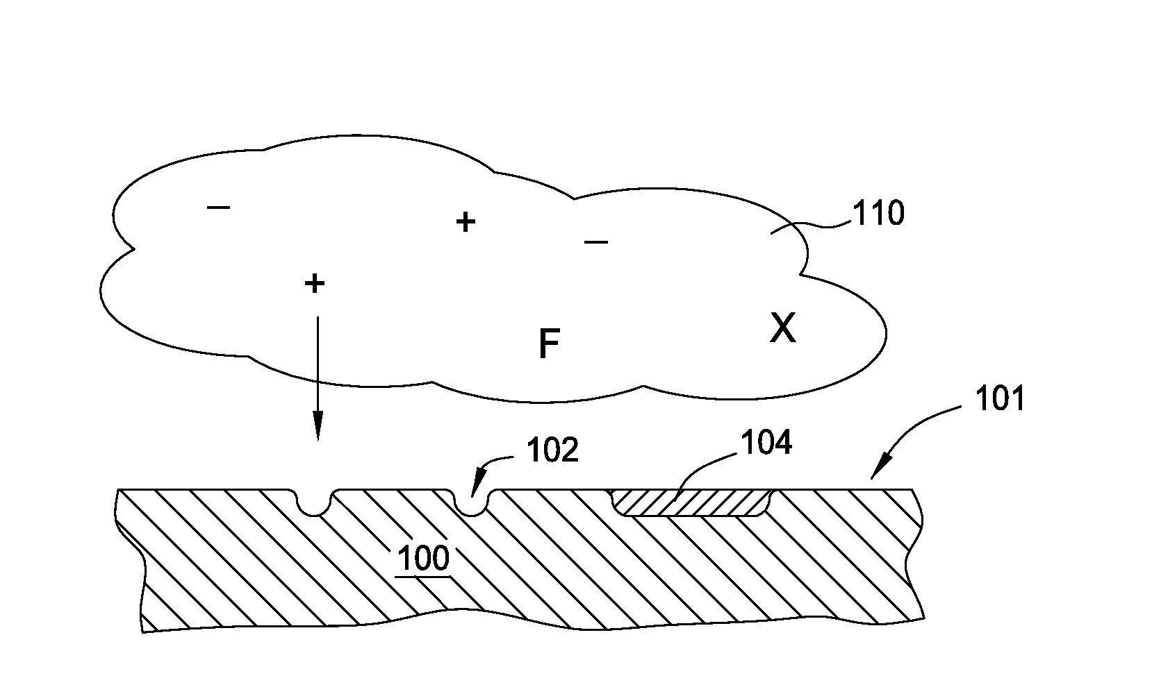
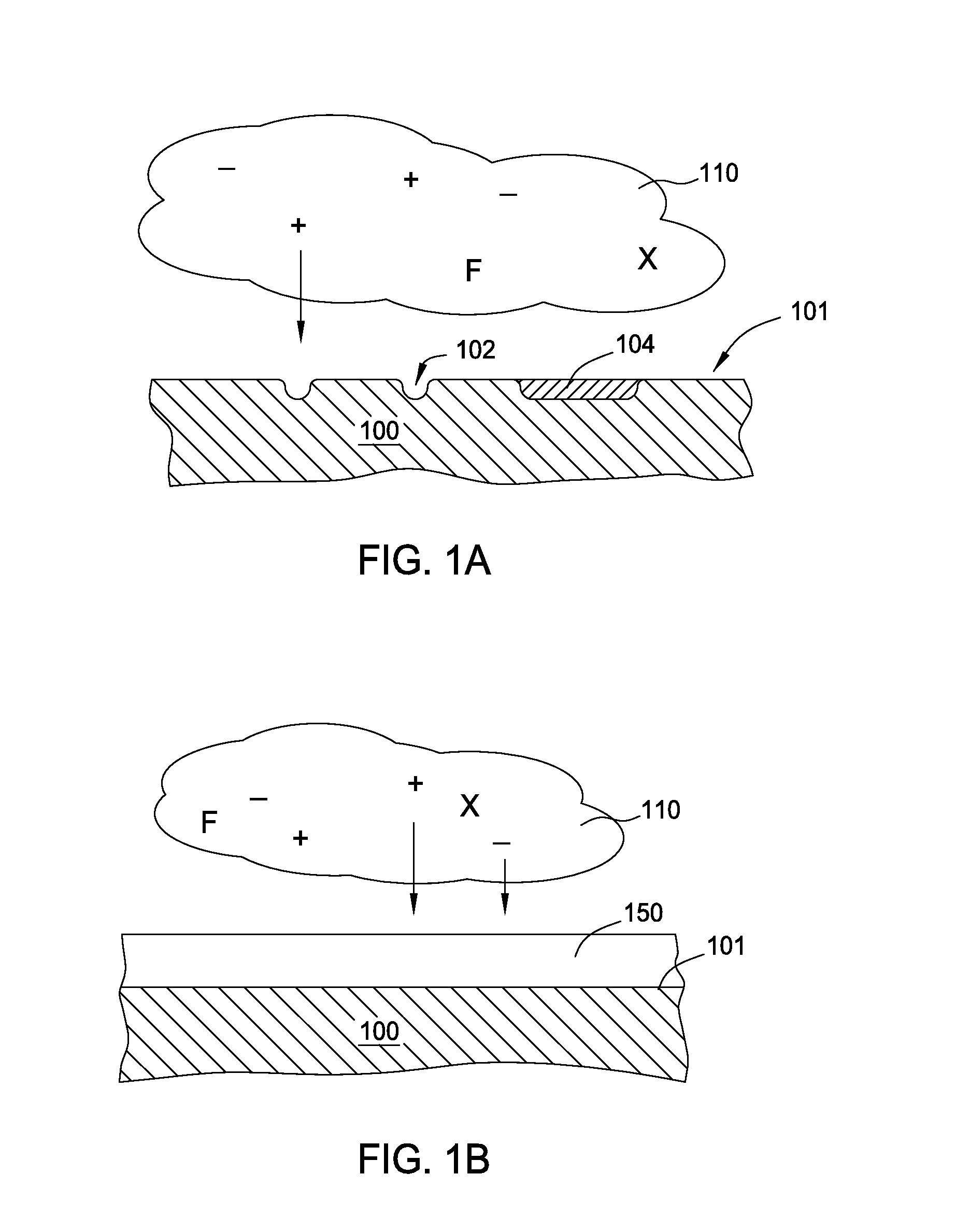
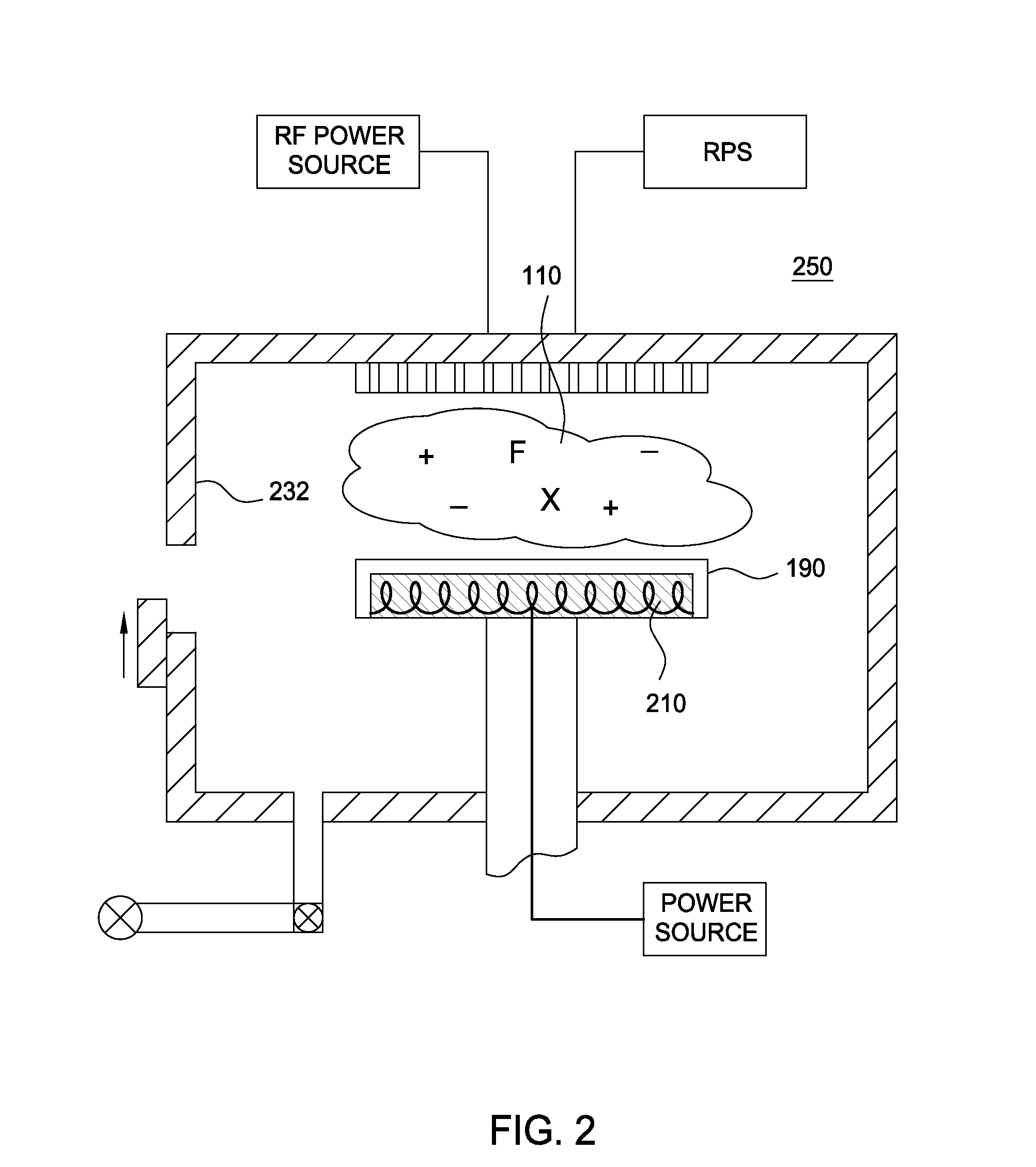
[0018]FIGS. 1A-B schematically illustrate the protective effects of a coating upon a chamber component. FIG. 1A depicts a partial cross sectional view of a conventional processing chamber component 100 exposed to a generally corrosive or reactive environment 110. For example, the chamber component 100 may be subjected to attack by species in the surrounding environment 110, which may result in pits 102 or other defects 104 formed on the surface 101 of the chamber component 100. Depending on the reactive environment 110, deterioration of the chamber component 100 may be caused by chemical or physical attacks, and may not necessarily result in readily visible defects such as those illustrated in FIG. 1A. For example, chemical or physica...


PUM

PropertyMeasurementUnit
Temperatureaaaaaaaaaa
Plasma poweraaaaaaaaaa

Abstract

Embodiments described herein relate to a protective coating that protects an underlying chamber component (i.e. the object upon which the coating is being deposited) from corrosion or deterioration within a corrosive environment.

Description

CROSS-REFERENCE TO RELATED APPLICATIONS[0001]This application claims benefit of U.S. provisional patent application Ser. No. 61 / 775,044, filed Mar. 8, 2013, which is herein incorporated by reference.BACKGROUND[0002]1. Field[0003]Embodiments described herein relate to a protective coating that protects an underlying chamber component (i.e. the object upon which the coating is being deposited) or component part from corrosion or deterioration within a corrosive environment.[0004]2. Description of the Related Art[0005]In semi-conductor chamber component processing systems, the interior of a processing chamber is often exposed to a variety of corrosive or reactive environments. These reactive environments may result from either stable corrosive gases, such as Cl2, or other reactive species, including radicals or by-products generated from process reactions. In plasma processing applications, such as etching or chemical vapor deposition (CVD), reactive species are also generated through ...

Claims


Application Information

Patent Timeline
IPC IPC(8): C23C16/50C23C16/08C23C16/40
CPCC23C16/50C23C16/08C23C16/409C23C16/403C23C16/045C23C16/30C23C16/4404C23C16/4405C23C16/56
Inventor NGUYEN, SON T.FONG, MICHAEL
Owner APPLIED MATERIALS INC
Learn More