Imaging lens and imaging aparatus
a technology of imaging apparatus and lens, applied in the direction of optics, instruments, optics, etc., can solve the problems of insufficient downsizing and the description of the lens system, and achieve the effects of reducing the overall lens length, wide angle, and high optical performan
- Summary
- Abstract
- Description
- Claims
- Application Information
AI Technical Summary
Benefits of technology
Problems solved by technology
Method used
Image

Examples
example 1
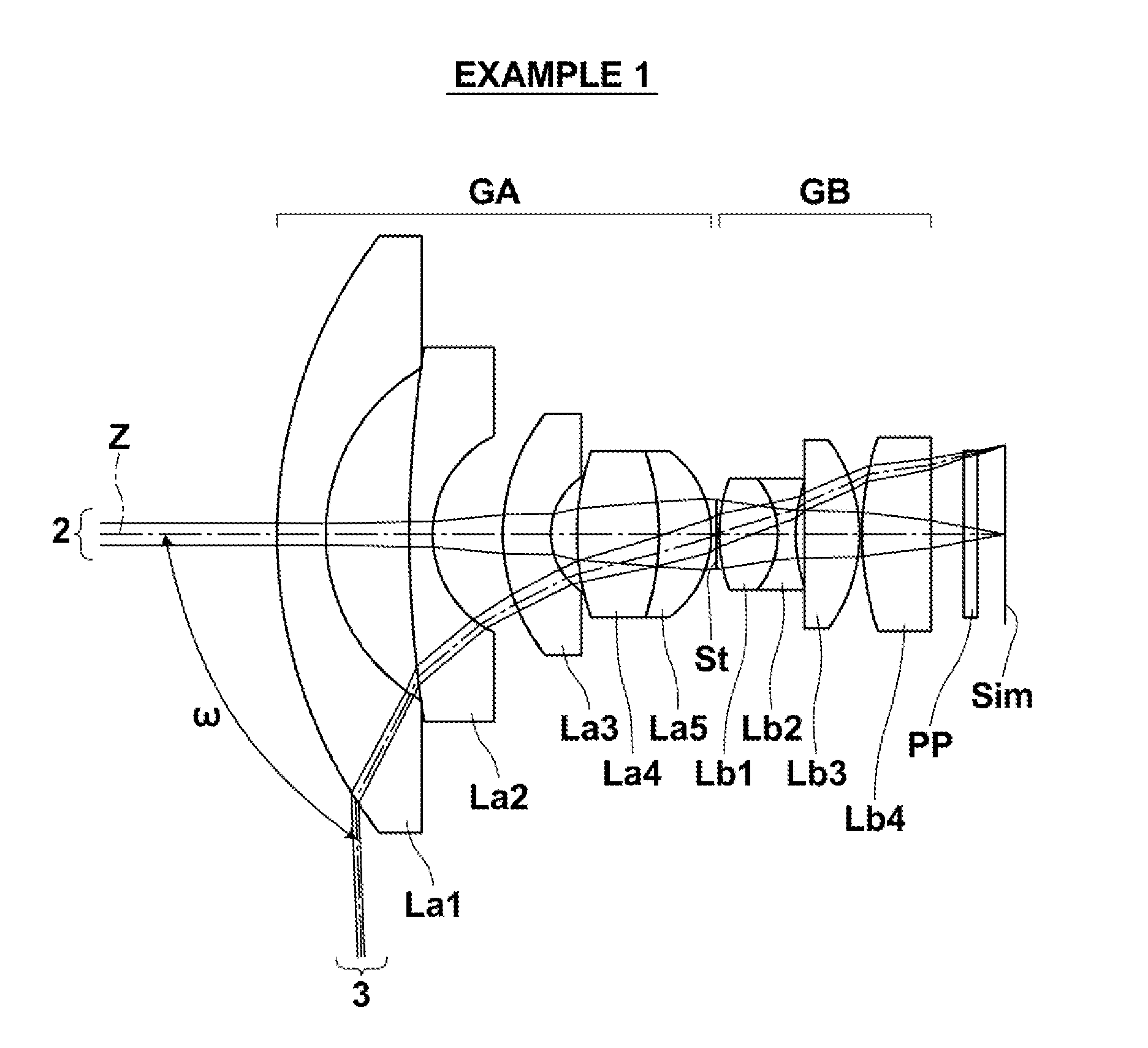
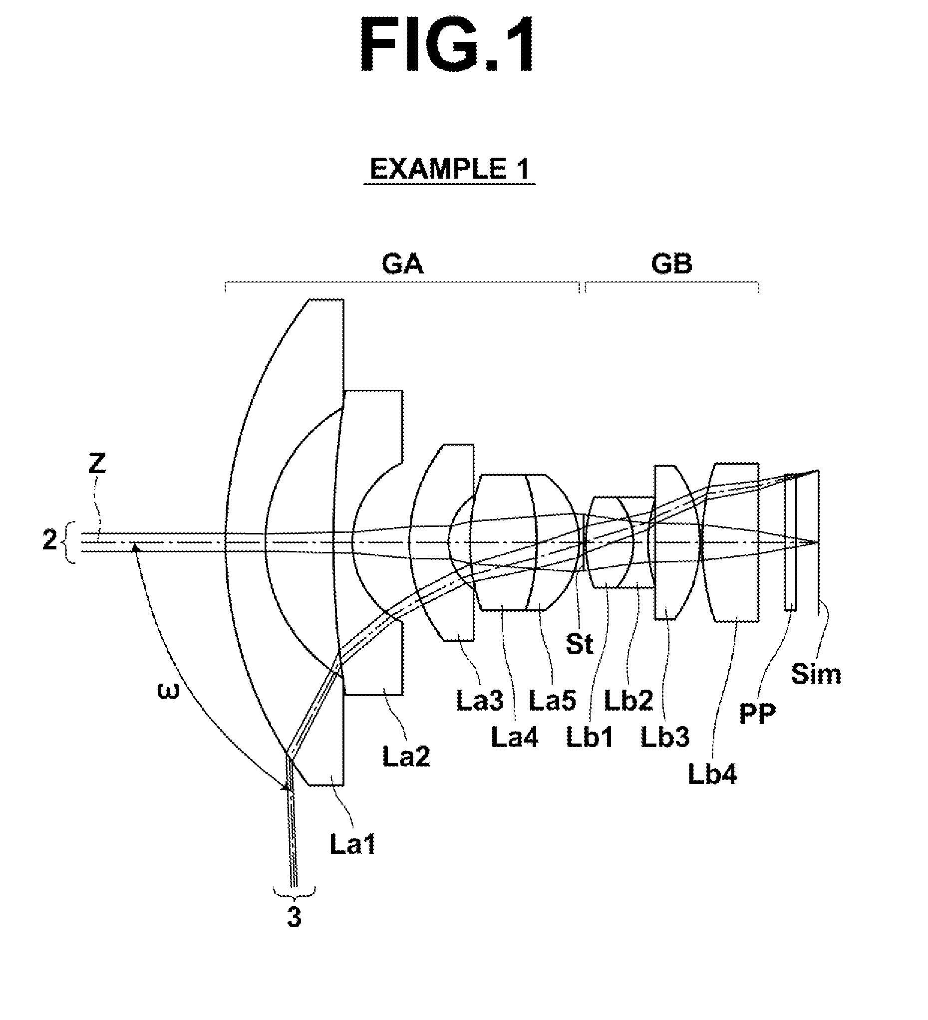
[0079]The configuration of the imaging lens of Example 1 is as illustrated in FIG. 1. The imaging lens of Example 1 includes a front group GA having a positive refractive power, an aperture stop St, and a rear group GB having a positive refractive power, disposed in order from the object side. The front group GA is composed of a lens La1 to a lens La5, disposed in order from the object side, while the rear group GB is composed of a lens Lb1 to a lens Lb4, disposed in order from the object side. The lenses constituting the imaging lens of Example 1 are all spherical lenses.
[0080]Table 1 shows lens data of the imaging lens of Example 1. Specs with respect to the d-line are given in the upper margin of Table 1, in which f represents the focal length of the entire system, Bf represents the back focus in terms of air equivalent distance, FNo. represents the F-number, and 2ω represents the maximum total angle of view when an object at infinity is in focus.
[0081]The Si column in Table 1 in...
example 2
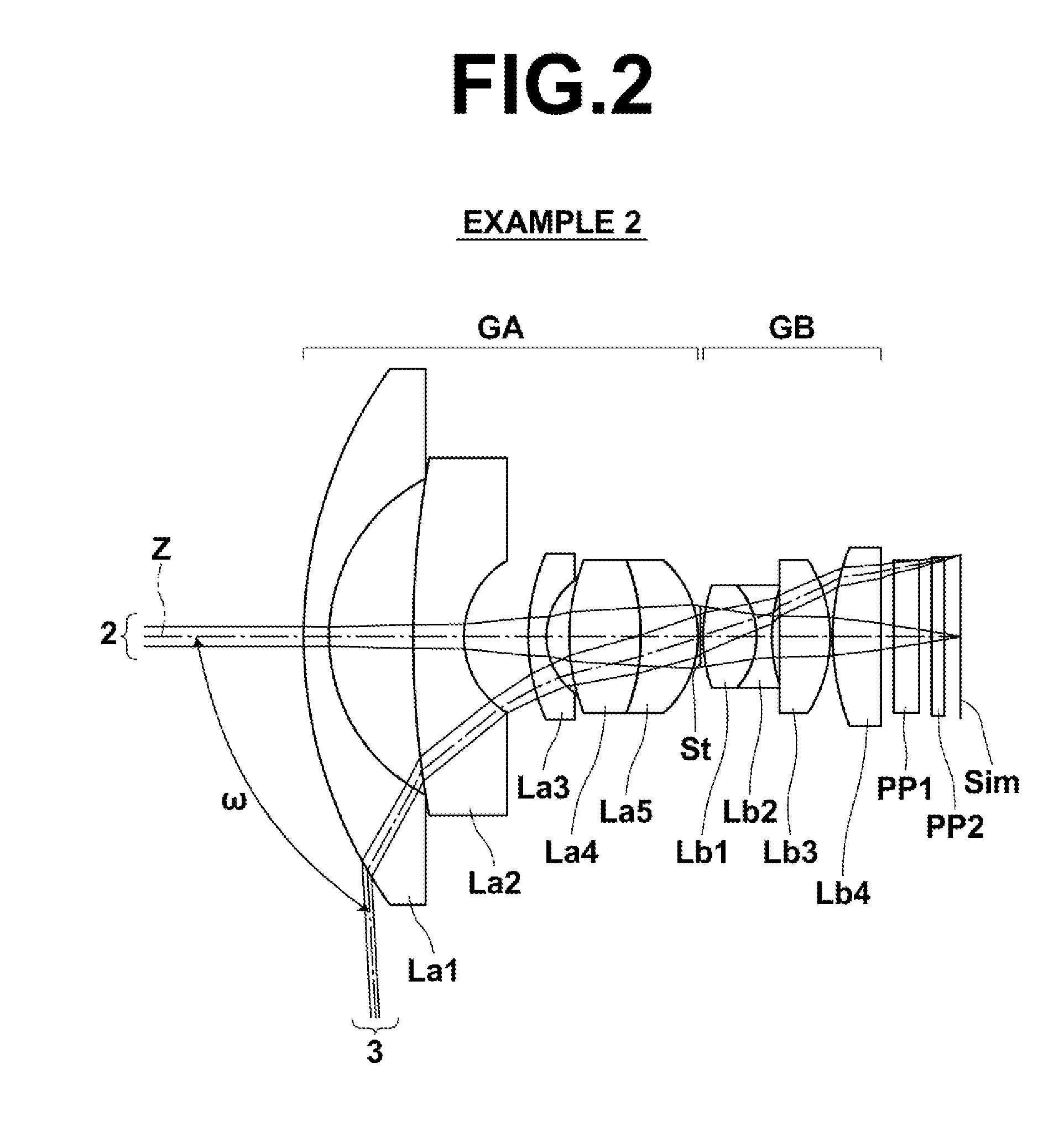
[0086]The configuration of the imaging lens of Example 2 is as illustrated in FIG. 2. Note that, in the example illustrated in FIG. 2, two parallel plate optical members PP1 and PP2 are disposed between the most image side lens surface and the image plane Sim, instead of the optical member PP of the example illustrated in FIG. 1. The imaging lens of Example 2 includes a front group GA having a positive refractive power, an aperture stop St, and a rear group GB having a positive refractive power, disposed in order from the object side. The front group GA is composed of a lens La1 to a lens La5, disposed in order from the object side, while the rear group GB is composed of a lens Lb1 to a lens Lb4 disposed in order from the object side. The lenses constituting the imaging lens of Example 2 are all spherical lenses.
[0087]Table 2 shows lens data of the imaging lens of Example 2. FIG. 5 shows aberration diagrams of the imaging lens of Example 2 when an object at infinity is in focus. In ...
example 3
[0088]The configuration of the imaging lens of Example 3 is as illustrated in FIG. 3. Note that, in the example illustrated in FIG. 3, two parallel plate optical members PP1 and PP2 are disposed between the most image side lens surface and the image plane Sim, instead of the optical member PP of the example illustrated in FIG. 1. The imaging lens of Example 3 includes a front group GA having a positive refractive power, an aperture stop St, and a rear group GB having a positive refractive power, disposed in order from the object side. The front group GA is composed of a lens La1 to a lens La4, disposed in order from the object side, while the rear group GB is composed of a lens Lb1 to a lens Lb4 disposed in order from the object side. The lenses constituting the imaging lens of Example 3 are all spherical lenses.
[0089]Table 3 shows lens data of the imaging lens of Example 3. FIG. 6 shows aberration diagrams of the imaging lens of Example 3 when an object at infinity is in focus. In ...
PUM
 Abstract
Description
Claims
Application Information
 - R&D
- Intellectual Property
- Life Sciences
- Materials
- Tech Scout
- Unparalleled Data Quality
- Higher Quality Content
- 60% Fewer Hallucinations
Browse by: Latest US Patents, China's latest patents, Technical Efficacy Thesaurus, Application Domain, Technology Topic, Popular Technical Reports.
© 2025 PatSnap. All rights reserved.Legal|Privacy policy|Modern Slavery Act Transparency Statement|Sitemap|About US| Contact US: help@patsnap.com