
Cable gland assembly

a technology of cable glands and components, applied in the direction of pipes, mechanical equipment, engine components, etc., can solve the problems of insufficient ip ratings of the aforesaid prior art designs, insufficient dynamic mechanical application, and segment deformation to lose its packing function, etc., to achieve enhanced protection, enhanced tensile strength, and relatively enhanced tensile strength

Active Publication Date: 2015-07-16
AVC INDAL CORP
View PDF2 Cites 23 Cited by
  • Summary
  • Abstract
  • Description
  • Claims
  • Application Information

AI Technical Summary

Benefits of technology

The present invention provides a cable gland assembly with multiple packing devices to provide enhanced protection against water, dust, and tensile forces. The assembly has a high IP rating and is suitable for dynamic mechanical and outdoor applications, as well as deep-water environments and high explosive atmospheres. The assembly includes a mounting member, a connection member, and an outer cap, with each packing device providing a layer of protection. The connection member increases the strength and protection of the assembly. Increasing the number of the connection member enhances the airtight strength for use in high explosive atmospheres and the watertight strength for use in deep-water environments. The assembly also prevents disconnection of the installed cable upon an impact.

Problems solved by technology

After installation of a cable in an electric box or any junction box of a machine, telecom or network system by means of a cable gland, the cable may be disconnected or loosened from the gland when stretched accidentally by an external force, causing leakage.
However, the aforesaid prior art designs simply has one packing ring set between the mounting member and the outer cap to wrap about the inserted cable, i.e., these prior art designs simply provide one single packing effect that is insufficient to firmly hold down the cable.
When the cable is stretched accidentally by an external force, a water leakage can occur.
However, because the first packing segment and the second packing segment are formed in one single packing member, the first packing segment and the second packing segment can be destructed to lose its packing functioning when the flexible conduit or cable is stretched by an external force.
However, the IP ratings of the aforesaid prior art designs are insufficient for dynamic mechanical application, or application in a deep-water environment or high explosive atmosphere.

Method used


Image

  • Cable gland assembly
  • Cable gland assembly
  • Cable gland assembly

Examples


Embodiment Construction

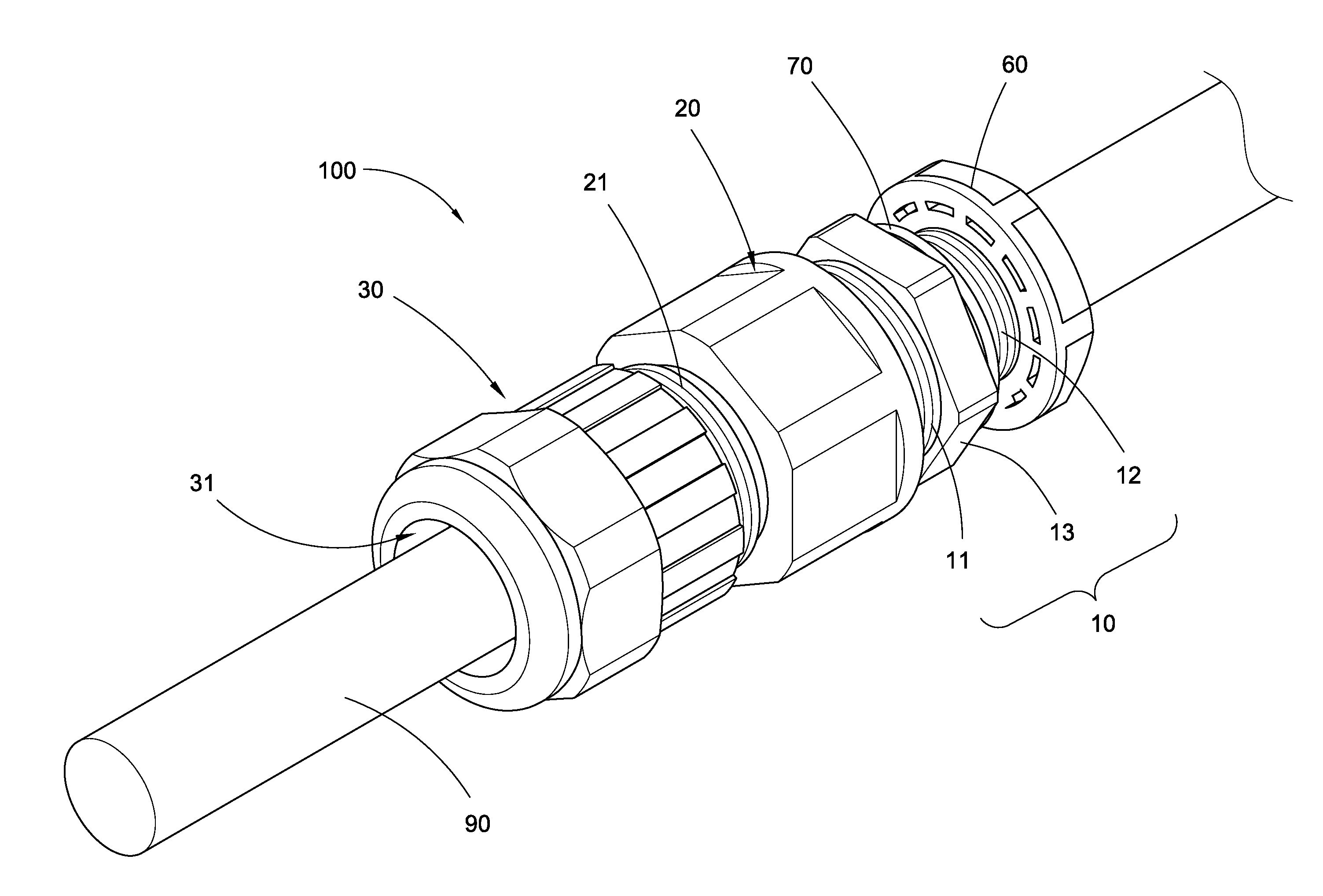
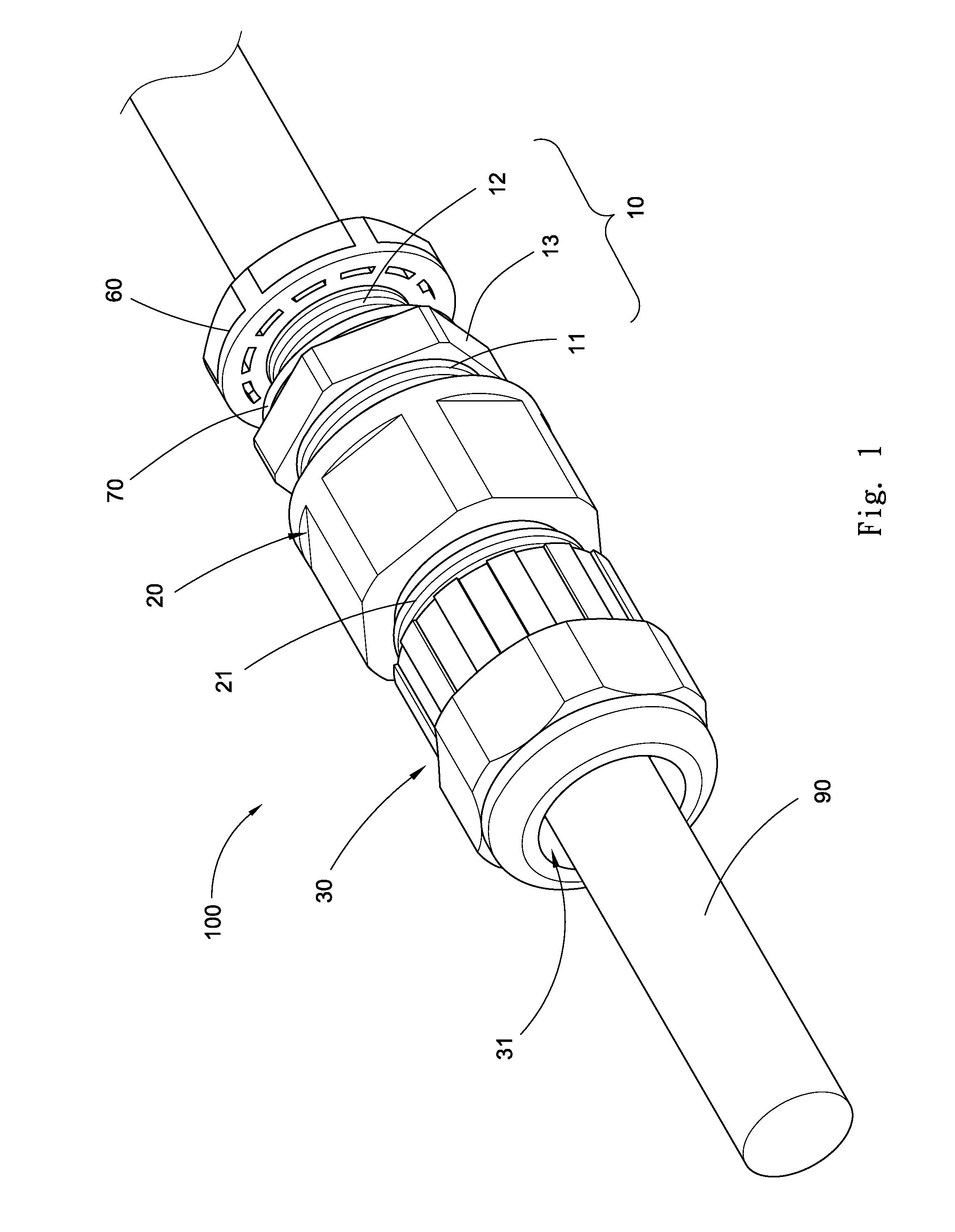
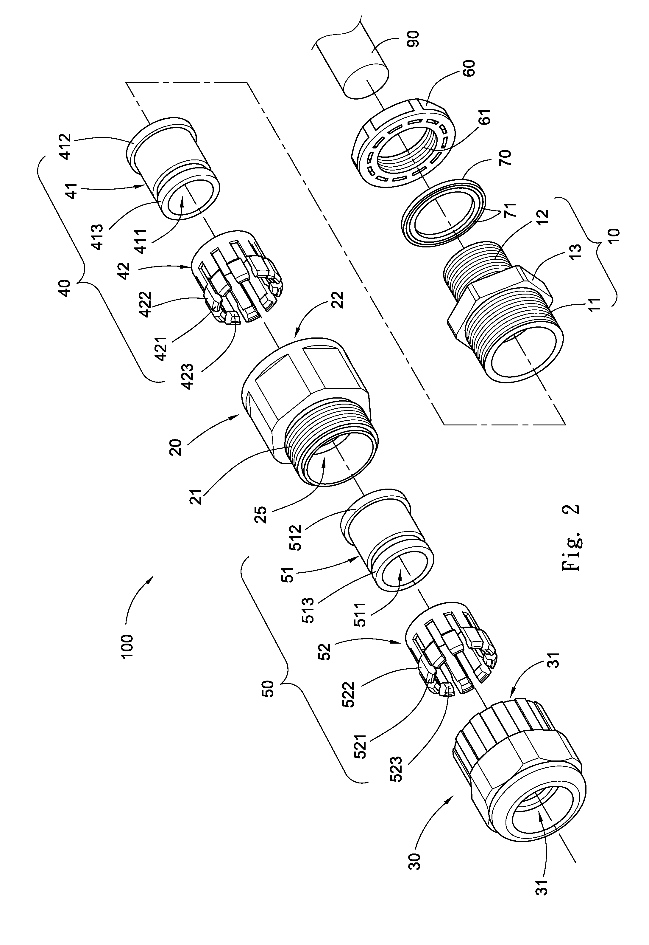
[0025]Referring to FIGS. 1-4, a cable gland assembly 100 in accordance with the present invention is shown. The cable gland assembly 100 comprises:

[0026]a mounting member 10 that is a tubular member mounted in a board member 80 of an electric box, machine, telecom box or network communication box, comprising a first outer thread 11;

[0027]a connection member 20 that comprises a second outer thread 21, a first axial hole 22, a second axial hole 25 in communication and axial alignment with the first axial hole 22, a first tapered surface 23 defined therein around one end of the first axial hole 22 and one end of the second axial hole 25, and a first inner thread 24 defined in the first axial hole 22 and threaded onto the first outer thread 11 of the mounting member 10;

[0028]an outer cap 30 that comprises an axial through hole 31 extending through two opposite ends thereof, a second tapered surface 32 defined in the axial through hole 31, and a second inner thread 33 defined in the axia...


PUM


Abstract

A cable gland assembly includes a mounting member mounted in a predetermined object, one or multiple connection members, an outer cap, and one first packing device and one or multiple second packing devices mounted in the mounting member between the connection members and the outer cap and compressible by the outer cap and the connection members to wrap about the periphery of an inserted cable and to provide multiple packing effects. Thus, the cable gland assembly has high IP rating, and is practical for dynamic mechanical application, or application in a deep-water environment or high explosive atmosphere.

Description

BACKGROUND OF THE INVENTION[0001]1. Field of the Invention[0002]The present invention relates to cable glands and more particularly, to a cable gland assembly, which provides enhanced protection and multiple packing, airtight, waterproof, dustproof and anti-tensile effects.[0003]2. Description of the Related Art[0004]After installation of a cable in an electric box or any junction box of a machine, telecom or network system by means of a cable gland, the cable may be disconnected or loosened from the gland when stretched accidentally by an external force, causing leakage. To avoid this problem, many improved cable gland designs are created, such as U.S. Pat. No. 5,927,892 entitled “Device for fastening a cable to a board”, U.S. Pat. No. 8,490,513 entitled “Cable gland and gasket ring assembly”, U.S. Pat. No. 8,288,667 entitled “Double-packing cable and flexible conduit gland”. These prior art designs commonly comprise a mounting member, a clamping member, a packing ring and an outer...

Claims


Application Information

Patent Timeline
Patent Type & Authority Applications(United States)
IPC IPC(8): H02G15/013H02G15/184F16J15/02
CPCF16J15/022H02G15/013H02G15/184
Inventor CHIU, TEH-TSUNG
Owner AVC INDAL CORP
Learn More