Print device and print method

a printing device and printing method technology, applied in printing, other printing apparatus, etc., to achieve the effect of high accuracy

Active Publication Date: 2015-07-09
MIMAKI ENG
View PDF3 Cites 0 Cited by
  • Summary
  • Abstract
  • Description
  • Claims
  • Application Information

AI Technical Summary

Benefits of technology

[0022](Configuration 8) A print method is configured to perform printing by an ink jet scheme, the print method including: outputting a drive signal being a signal for causing a piezoelectric element to be displaced to an ink jet head including a nozzle that discharges ink droplets, an ink chamber that stores ink droplets at an upstream of the nozzle, and the piezoelectric element that causes ink in the ink chamber to be discharged from the nozzle. The drive signal is a signal that includes a discharge driving signal for causing the piezoelectric element to be displaced so that an ink droplet is discharged from the nozzle, and a post-discharge controlling signal for caus...

Problems solved by technology

In the configuration of JP-A2009-113426, for a case of using a drive signal formed of a trapezoidal wave, a drive signal formed of plural types of ...

Method used


Image

  • Print device and print method
  • Print device and print method
  • Print device and print method

Examples


Embodiment Construction

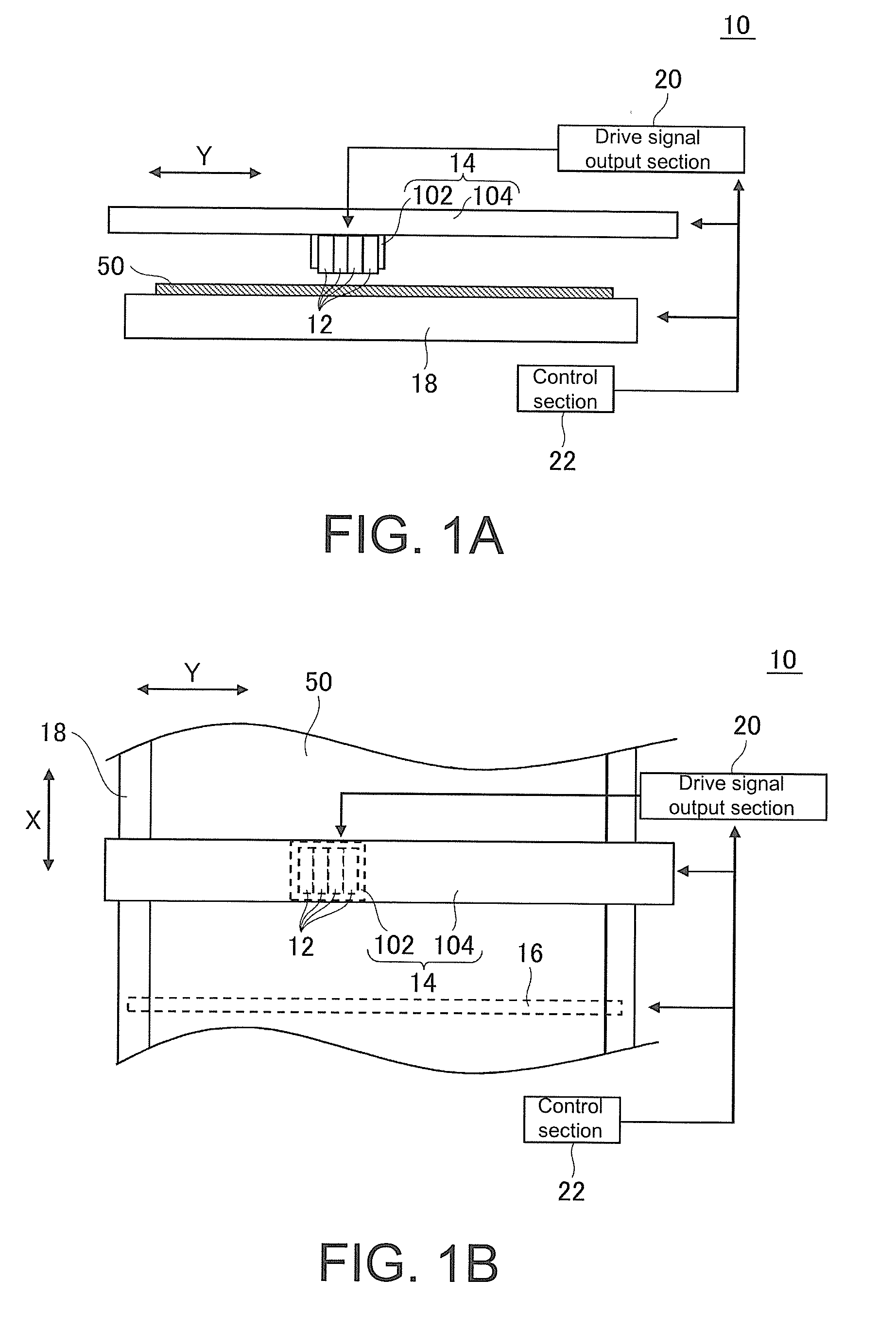
[0030]Herein below, embodiments of the present invention will be described with reference to the drawings. FIG. 1A and FIG. 1B show an example of a print device 10 according to an embodiment of the present invention. FIG. 1A and FIG. 1B are a front diagram and a top diagram showing the example of a configuration of a primary part of the print device 10.

In this example, the print device 10 is an ink jet printer that performs printing by an ink jet scheme, and includes a plurality of ink jet heads 12, a main scan driving section 14, a sub scan driving section 16, a platen 18, a drive signal output section 20, and a control section 22.

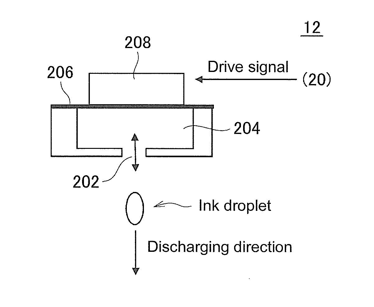
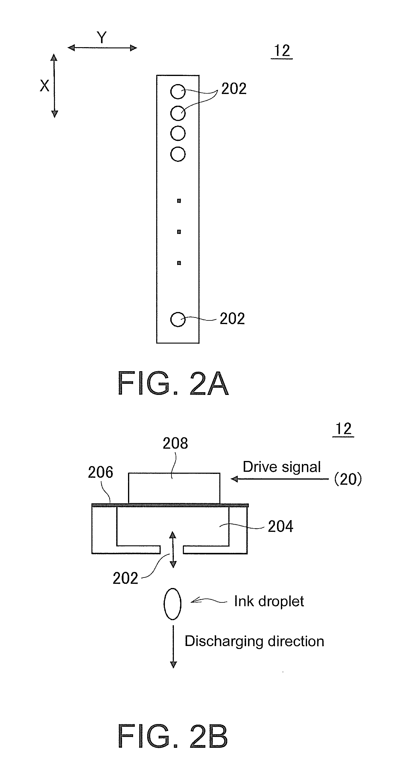
[0031]The plurality of ink jet heads 12 is ink jet heads that each discharge ink droplets of respective colors used in printing. In this example, the plurality of ink jet heads 12 is arranged to align in a main scanning direction that is predetermined set (Y direction in the drawings). Further, each of the ink jet heads 12 has nozzles for discharging the ...


PUM


Abstract

A print device is configured to perform printing by an ink jet scheme including: an ink jet head including a nozzle, an ink chamber that stores ink droplets at an upstream of the nozzle, and a piezoelectric element; and a drive signal output section that outputs a drive signal for causing the piezoelectric element to be displaced. The drive signal includes a discharge driving signal for causing the piezoelectric element displaced so that ink droplets are discharged from the nozzle, and a post-discharge controlling signal for causing the piezoelectric element displaced after the ink droplets are discharged from the nozzle, the drive signal output section outputs the discharge driving signal by which a voltage changes linearly from a first voltage to a second voltage which are predeterminedly set, at a timing when the ink droplets are to be discharged from the nozzle, and outputs a substantial sine wave.

Description

CROSS-REFERENCE TO RELATED APPLICATION[0001]This application claims the priority benefit of Japan application serial no. 2014-001427, filed on Jan. 8, 2014. The entirety of the above-mentioned patent application is hereby incorporated by reference herein and made a part of specification.BACKGROUND OF THE INVENTION[0002](1) Field of the Invention[0003]The present invention relates to a print device and a print method.[0004](2) Description of Related Art[0005]In the recent years, an ink jet printer that performs printing by an ink jet scheme is widely used. In the ink jet printer, ink droplets are discharged from a nozzle by driving a drive element (piezoelectric element and the like) provided at a position of the nozzle of the ink jet head. In this case, as a drive signal for driving the drive element, for example, a trapezoidal wave and the like is widely used. Further, conventionally, a configuration that uses a drive signal (potential signal) configured of plural types of sine wav...

Claims


Application Information

Patent Timeline
IPC IPC(8): B41J2/045
CPCB41J2/04581B41J2/04541B41J2/04588B41J2/04596
Inventor OHNISHI, MASARU
Owner MIMAKI ENG
Why Eureka
Try Eureka