Flow sensor and control system of internal combustion engine
a control system and flow sensor technology, applied in the direction of machines/engines, liquid/fluent solid measurement, instruments, etc., can solve the problems of reducing size and cost, difficult to manufacture these bridge circuits, and increasing the requirement. , to achieve the effect of low cos
- Summary
- Abstract
- Description
- Claims
- Application Information
AI Technical Summary
Benefits of technology
Problems solved by technology
Method used
Image

Examples
first embodiment
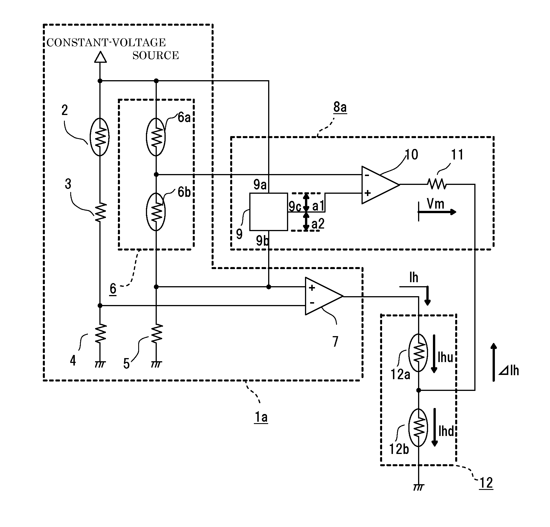
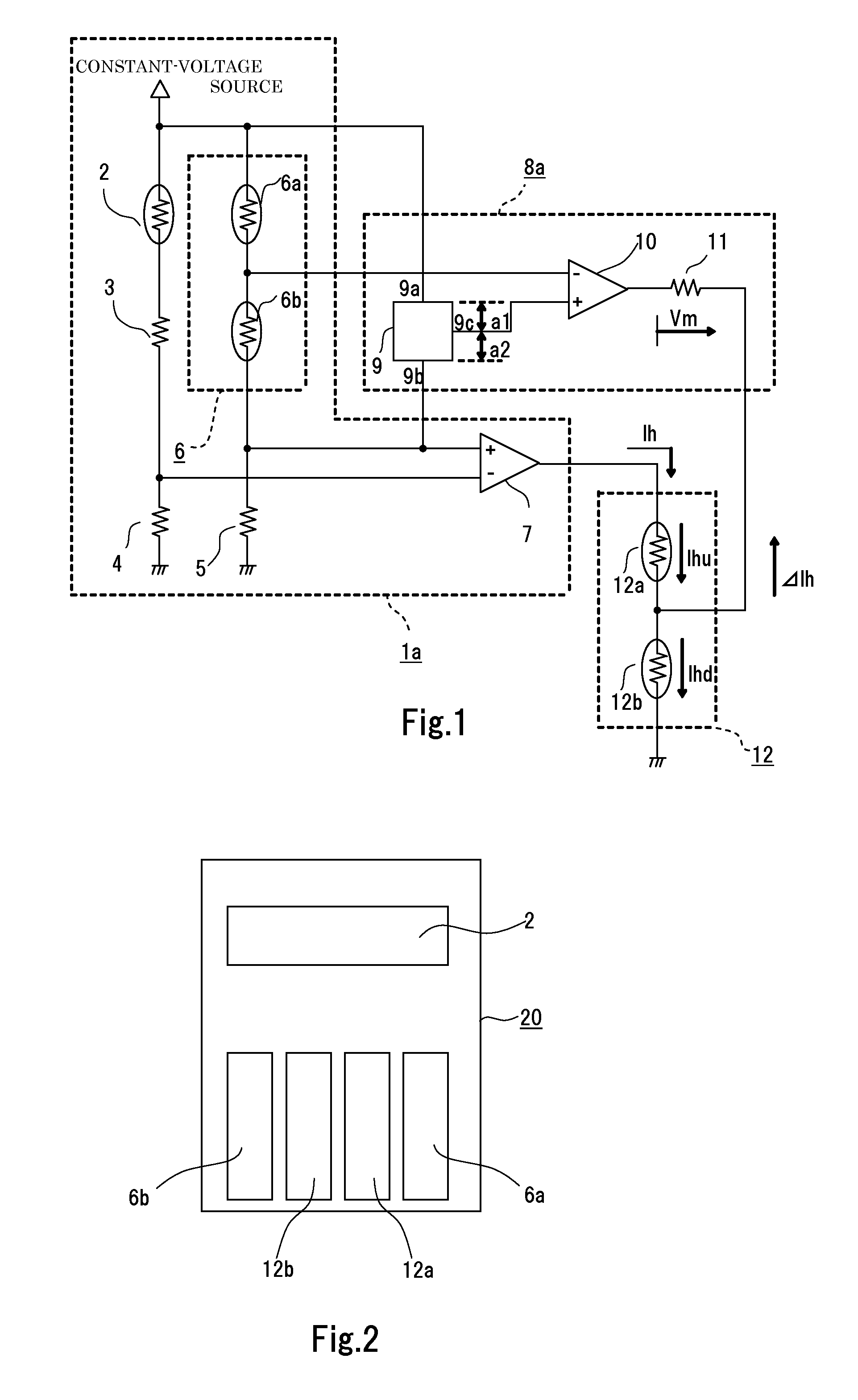
[0033]Hereinafter, a flow sensor according to a first embodiment of the invention will be described with reference to FIG. 1 through FIG. 9. The flow sensor of the invention is a thermal flow sensor of a heating current detection type. FIG. 1 is a view showing a configuration of a flow rate detection circuit in the flow sensor according to the first embodiment of the invention, and the configuration of the flow rate detection circuit will be described first using this drawing.
[0034]The flow sensor according to the first embodiment of the invention includes a fluid temperature detection portion 2 that detects a temperature of a fluid, upstream and downstream heating elements (first and second heating elements) 12a and 12b disposed, respectively, upstream and downstream in a flow direction of the fluid so as to undergo mutual thermal interference, an upstream temperature detection portion (first temperature detection portion) 6a disposed at a position under the influence of heat from ...
second embodiment
[0066]FIG. 10 is a view showing a configuration of a flow rate detection circuit in a flow sensor according to a second embodiment of the invention. Reference numerals of FIG. 10 same as those of FIG. 1 denote same or equivalent portions and a description is omitted herein.
[0067]The first embodiment above has described the control by the average temperature control portion 1a by way of example, according to which the heating currents Ihu and Ihd flown, respectively, through the upstream and downstream heating elements 12a and 12b are controlled so that an average temperature of the upstream and downstream temperature detection portions 6a and 6b is maintained at a temperature predetermined degrees higher than a temperature of the fluid detected by the fluid temperature detection portion 2. It should be noted that the second embodiment is characterized in that an average temperature control portion (first control portion) 1b performs control using an average temperature of the upstre...
third embodiment
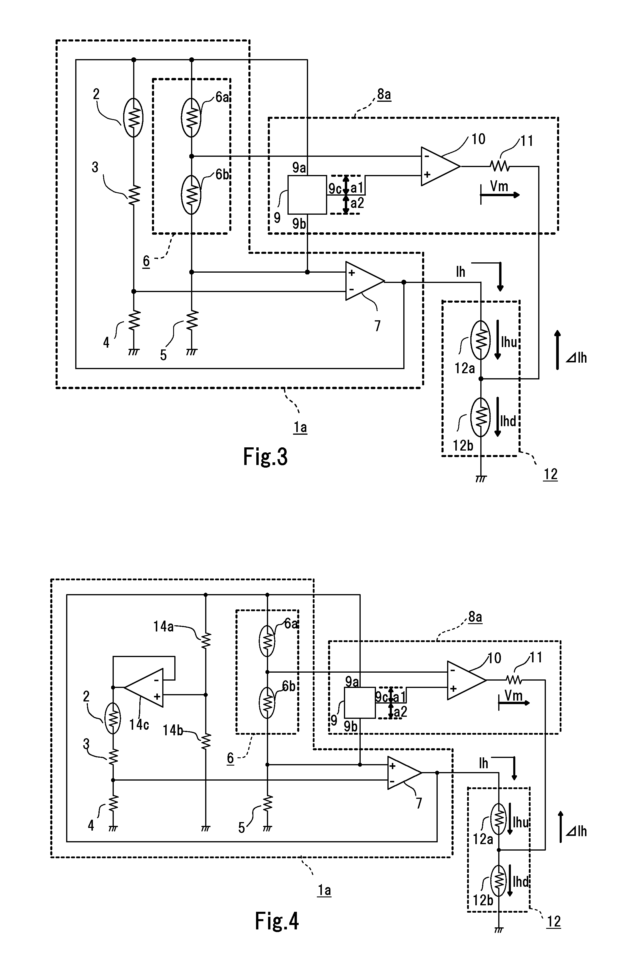
[0083]FIG. 11 is a view showing a configuration of a flow rate detection circuit in a thermal flow sensor according to a third embodiment of the invention. Reference numerals of FIG. 11 same as those of FIG. 1 denote same or equivalent portions and the average temperature control portion 1a is the same as the counterpart of the first embodiment above shown in FIG. 1, and a description is omitted herein.
[0084]The first embodiment above has described the control by the voltage ratio control portion 8a by way of example, according to which the heating currents Ihu and Ihd flown, respectively, through the upstream and downstream heating elements 12a and 12b are controlled so that a temperature difference between the upstream and downstream temperature detection portions 6a and 6b or a voltage ratio between the upstream and downstream temperature detection portions 6a and 6b takes a predetermined value. It should be noted that the third embodiment is characterized in that a voltage ratio...
PUM
 Abstract
Description
Claims
Application Information
 - R&D
- Intellectual Property
- Life Sciences
- Materials
- Tech Scout
- Unparalleled Data Quality
- Higher Quality Content
- 60% Fewer Hallucinations
Browse by: Latest US Patents, China's latest patents, Technical Efficacy Thesaurus, Application Domain, Technology Topic, Popular Technical Reports.
© 2025 PatSnap. All rights reserved.Legal|Privacy policy|Modern Slavery Act Transparency Statement|Sitemap|About US| Contact US: help@patsnap.com