
Heat exchanger

Inactive Publication Date: 2015-07-02
MAHLE INT GMBH
View PDF11 Cites 19 Cited by
  • Summary
  • Abstract
  • Description
  • Claims
  • Application Information

AI Technical Summary

Benefits of technology

The present invention aims to provide a heat exchanger that has a high thermal capacity without being heavy or expensive in materials. This helps to improve the efficiency of the heat exchanger.

Problems solved by technology

In both solutions, the exhaust gas channels are surrounded by a coolant-conducting housing, which has a substantial weight and contributes greatly to the cost during the production of the exhaust gas heat exchanger.

Method used


Image

  • Heat exchanger
  • Heat exchanger
  • Heat exchanger

Examples


Embodiment Construction

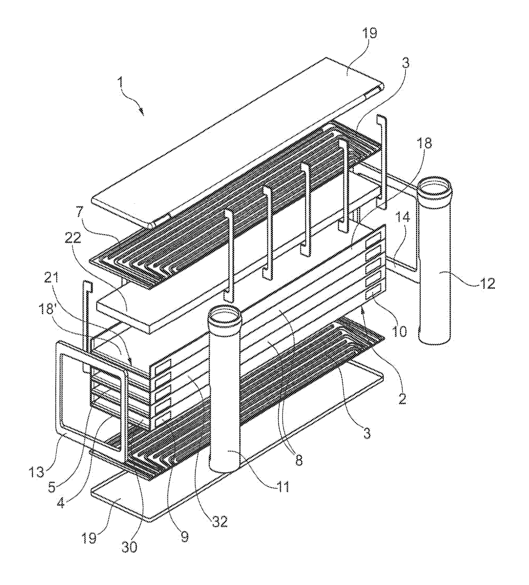
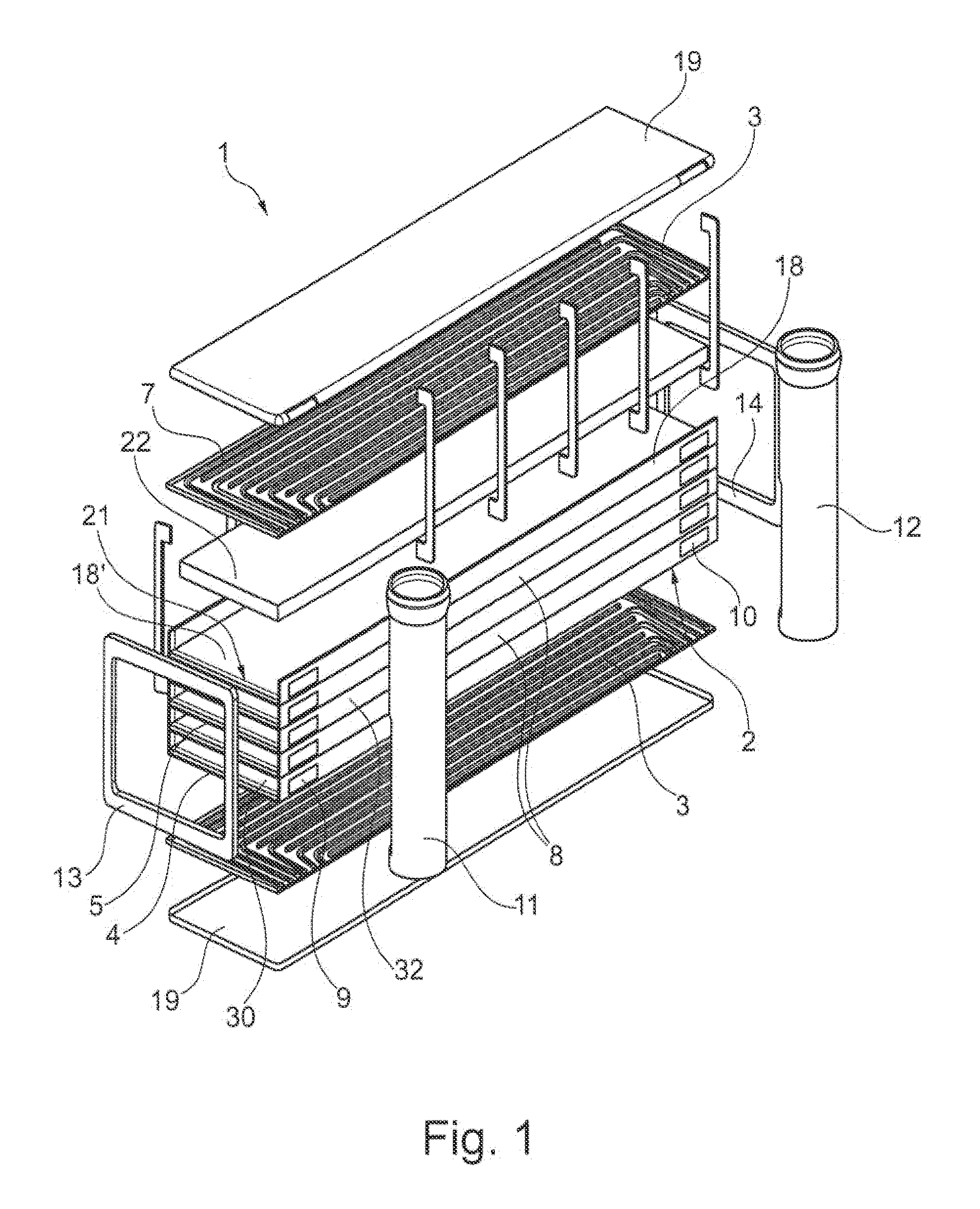
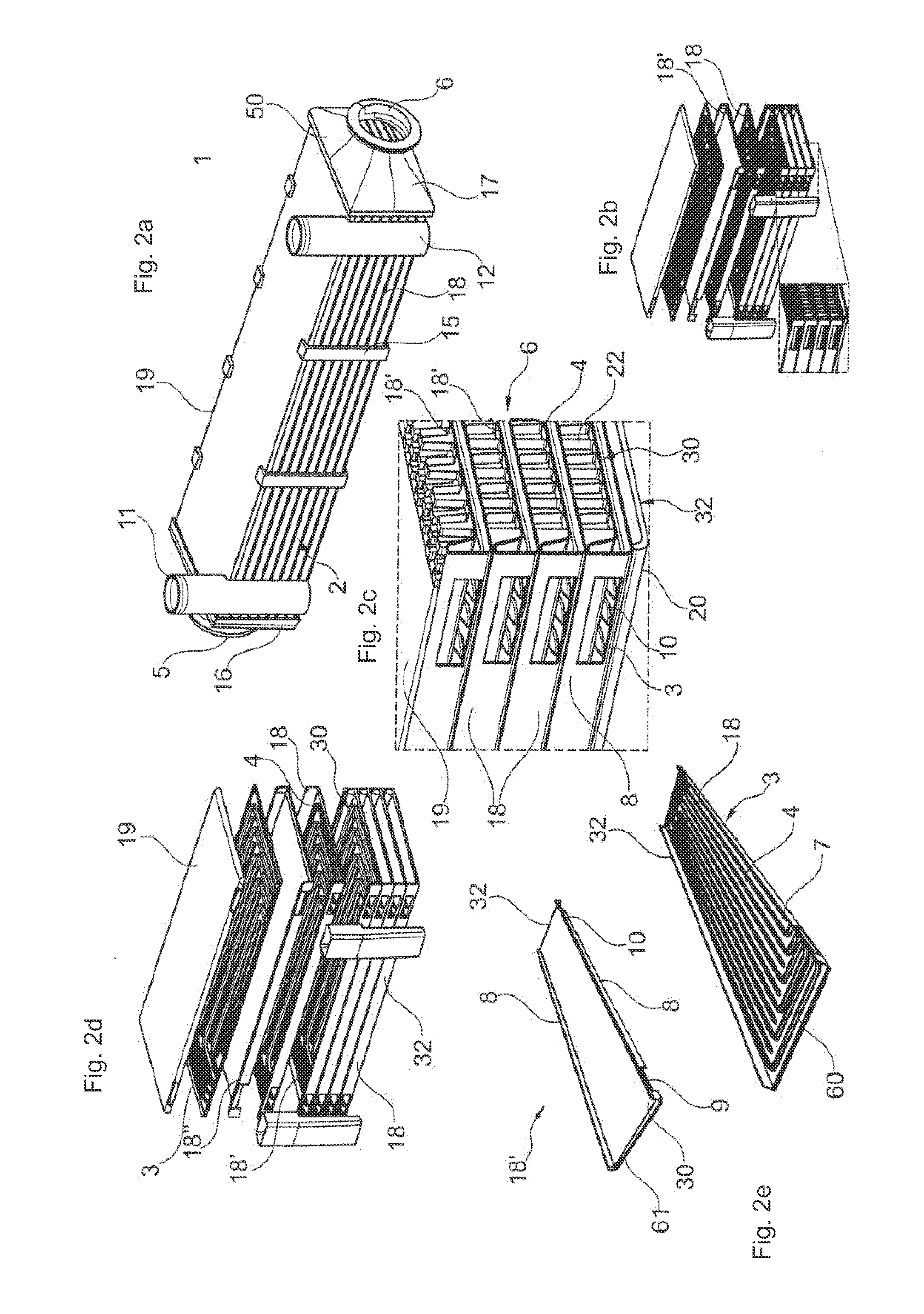
[0051]FIG. 1 shows an exemplary embodiment of a heat exchanger 1 of the invention, which can be formed as an exhaust gas cooler or as a charge air cooler. Alternatively, heat exchanger 1 can also be used in another way. It is advantageous if a gaseous fluid is used as a first fluid. In this case, exhaust gas or air, such as charge air, can be used as the first gaseous fluid. It is also advantageous if a liquid fluid is used as the second fluid. Water or a water-based mixture used as a coolant or another coolant or a refrigerant can be employed for this purpose.

[0052]Such a heat exchanger 1 can be used advantageously as an exhaust gas heat exchanger in a motor vehicle. Within the scope of a so-called exhaust gas recirculation system (EGR system), the exhaust gas discharged from the internal combustion engine of the motor vehicle can be cooled at least partially by a liquid coolant of a coolant circuit in the heat exchanger and be again supplied to the intake tract of the internal com...


PUM


Abstract

A heat exchanger, in particular an exhaust gas cooler or charge air cooler, is provided that includes a plate stack which has a plurality of elongated plate pairs, each set of two interconnected plates forming a respective second fluid channel between themselves, and a first fluid channel being formed between two plate pairs, a first fluid channel being surrounded by two second fluid channels, each second fluid channel being connected to at least one manifold.

Description

[0001]This nonprovisional application is a continuation of International Application No. PCT / EP2013 / 066289, which was filed on Aug. 2, 2013, and which claims priority to German Patent Application No. 10 2012 216 589.4, which was filed in Germany on Sep. 17, 2012, and which are both herein incorporated by reference.BACKGROUND OF THE INVENTION[0002]1. Field of the Invention[0003]The invention relates to a heat exchanger, particularly a charge air cooler or an exhaust gas cooler for a motor vehicle.[0004]2. Description of the Background Art[0005]An exhaust gas heat exchanger, which consists of a stack surrounded by a housing, is known from EP 1 348 924 B1, which corresponds to U.S. Pat. No. 6,920,918, whereby the stack is formed of flat tubes and each flat tube contains a turbulator, whereby the exhaust gas flows through each flat tube. A coolant channel, designed with flow directing elements through which the coolant taking up the heat of the exhaust gas is conducted, is formed in eac...

Claims


Application Information

Patent Timeline
IPC IPC(8): F28D9/00F02M25/07F02B29/04F28F9/02
CPCF28D9/0062F02B29/045F02M25/0734F28F9/02F02B29/0462F28D9/0037F28D21/0003F28D2021/0082F28F3/025F28F3/046F28F9/0243F28F2275/04F28F2009/0297F02M26/29F02M26/32Y02T10/12
Inventor BARWIG, JUERGENENSMINGER, STEFFENMAUCHER, ULRICHSCHMID, MATTHIAS
Owner MAHLE INT GMBH
Learn More