
Auger cleaning device for removing debris from a helical drilling tool, drilling machine provided with said cleaning device and use of said drilling machine

Active Publication Date: 2015-06-25
SOILMEC
View PDF3 Cites 13 Cited by
  • Summary
  • Abstract
  • Description
  • Claims
  • Application Information

AI Technical Summary

Benefits of technology

The present invention relates to an auger cleaning device for drilling machines. The device includes a roller and a blade or plough that rotate on the screw of the drilling tool. The cleaning tool can be opened and closed to clean the machine. The device improves the efficiency and reliability of drilling machines by preventing clogging and damage to the machine. The invention also includes a drilling machine with the cleaning device and a control unit for controlling the rotation of the cleaning tool. The cleaning device can be used with different types of drilling machines and is adaptable to different conditions. The technical effects of the invention include improved efficiency, reliability, and adaptability of drilling machines.

Problems solved by technology

This method performs well when it is necessary to drill holes with a medium-small diameter, in cohesive ground but also in incoherent ground or in general in ground with a high possibility of collapsing inside the hole that is being made.
The depths do not normally exceed 35 metres, both due to the fact that the length of the auger is proportional to that of the tower and this implies a machine size that is increasingly greater, with difficulties in terms of transportation and having high costs, and due to the fact that the auger full of earth has a weight such as to require a considerable extraction force (and multiple) that is increasingly greater.
It is not permissible for the workers to move below an auger that is even more than 35 metres high with the threat of falling debris (not only blocks of clay but also gravel, pebbles or small masses of rocks and ground) with a considerable weight and which fill the turns.
The rotation however generates problems when carrying out the casting and is not always admissible.
The effectiveness of this type of device is commonly recognised but it has the drawback of reducing the stroke of the rotary along the tower and consequently the drilling depth, by a measurement that is equal to its bulk in height.
This means that in order to clean the auger, this must be set in rotation, or even better in counter-rotation with respect to the drilling direction and therefore without a provision for blocking the fall, the debris tends to drop in the hole obtained, jeopardising the qualities of the cast of concrete that at the end will have inclusions of ground in it.
In the presence of a substantial volume of particularly cohesive debris, the system may not have enough potential energy for cleaning the auger.
In some cases it is required for there to be the axial block of the cleaner with respect to the tower so as to best counteract the forces of the ground and in this case its position is positioned above the lower guides present on the mast and the lost drilling height can reach up to 5 m. Moreover, since this system does not have the possibility of staying in background with respect to the disc of the auger, it occupies part of the height of the auger itself and consequently reduces the depth of the drilling.

Method used


Image

  • Auger cleaning device for removing debris from a helical drilling tool, drilling machine provided with said cleaning device and use of said drilling machine
  • Auger cleaning device for removing debris from a helical drilling tool, drilling machine provided with said cleaning device and use of said drilling machine
  • Auger cleaning device for removing debris from a helical drilling tool, drilling machine provided with said cleaning device and use of said drilling machine

Examples


first embodiment

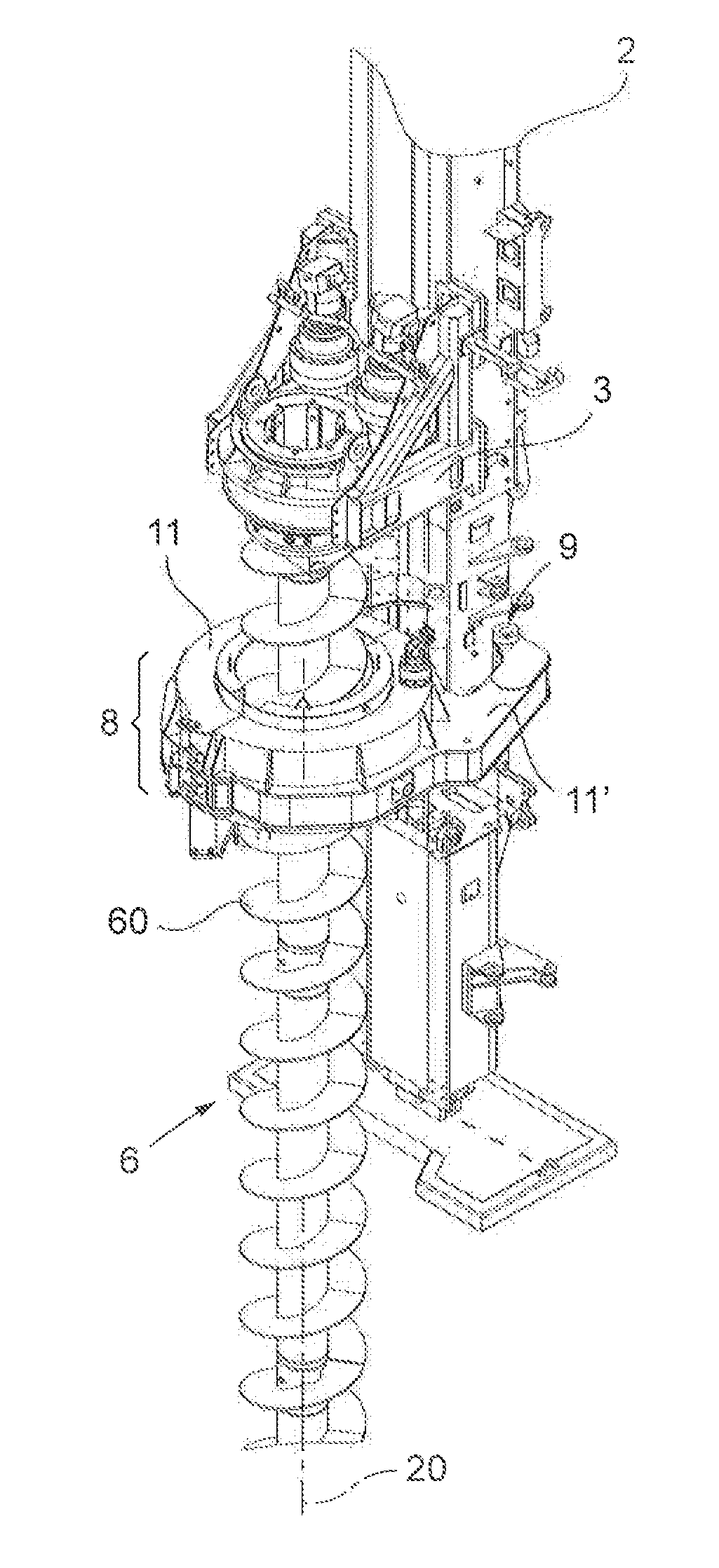
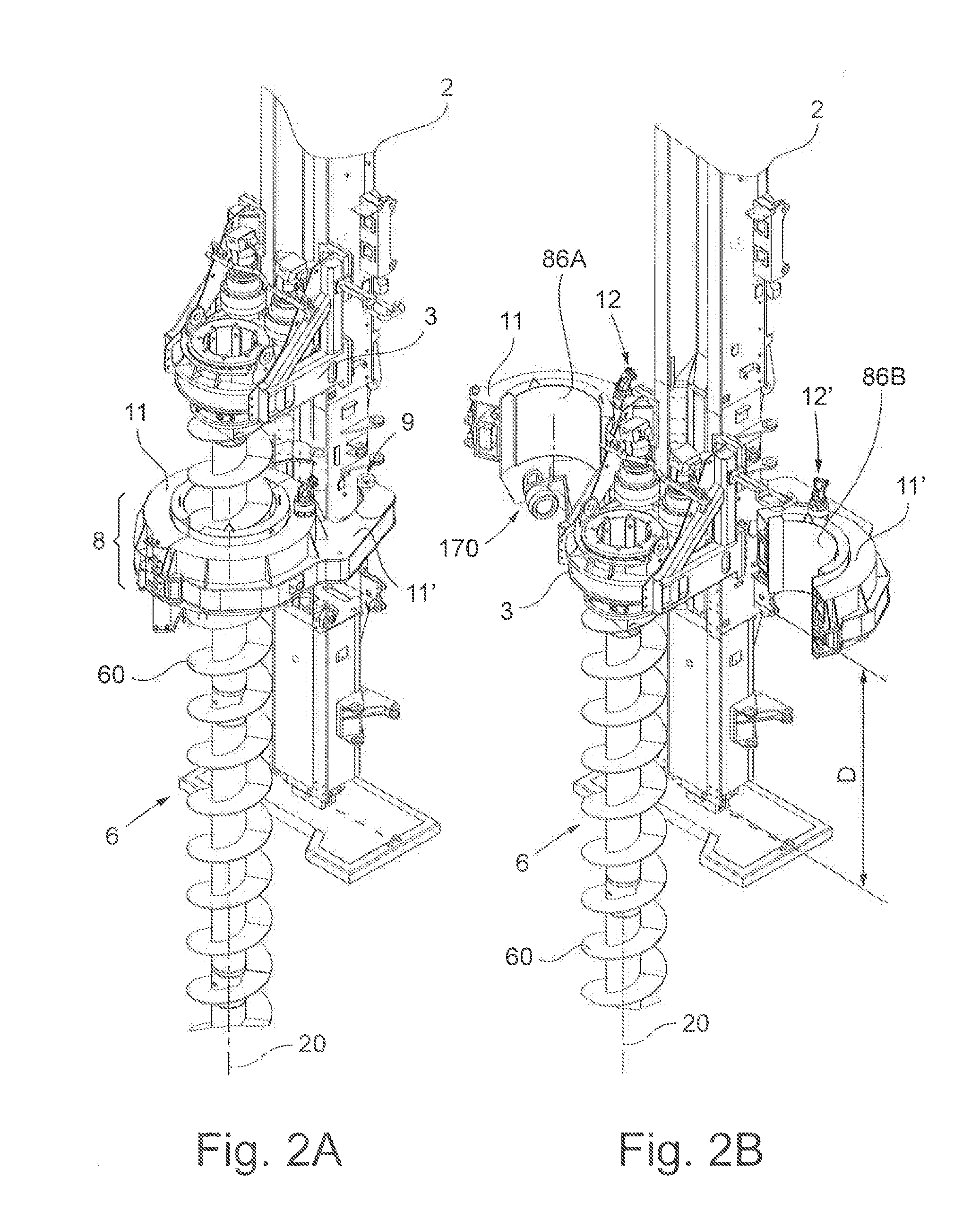
[0046]FIGS. 2A, 2B 3-7, 10, 10A are relative to an auger cleaning device according to the invention, wholly indicated with reference numeral 8.

[0047]The drilling tool 6 shown in FIGS. 2A, 2B comprises an auger with a single thread or single-start 60 but, in embodiments that are not shown, it can comprise screws with many threads, i.e. with multi-starts.

[0048]According to one aspect of the invention, the auger cleaning device 8, 8′, 800, 800′ in brief in the present description also indicated as cleaner 8,8′,800,800′” or “auger cleaner 8,8′,800,800′”, comprises:[0049]a tool-holder support;[0050]at least one cleaning tool 170 constrained to the tool-holder support.

[0051]The cleaning tool (170) is arranged for being actuated by an actuation system (12,12′,4).

[0052]The tool-holder support is arranged for reversibly passing from an open configuration to a closed configuration so that:[0053]in the closed configuration the tool-holder support forms a pass-through opening 82 that is arrange...

second embodiment

[0083]FIGS. 8, 8A are relative to a cleaner 8′ according to the invention, in which the movement of the cleaning roller is given to at least one actuator (12″) of the magnetic movement type to manage, preferably comprising a stator 35, 35′ and at least one magnet 34 that form one or more torque motors with a system of the “direct drive” type. A static part 80′A, which is hinged to the tower 2 through pins 9 and preferably driven to be opened / closed by cylinders or actuators 10—pins and actuators not shown, but for example identical to the previous ones—is located, in its operative condition, around the axis 20 of a hypothetical auger 6, in a form in which it is wound around the sleeve, identifying a pass-through opening 82. Like in the previous figures, the cleaner 8′ can comprise at least two parts, in the simplified non limiting representation exactly two, of which for the sake of simplicity of representation, only one is represented. One rotating part 31, also indicated as a roto...

embodiment 800

[0113]In the case in which the cleaning device can slide on the tower, for example in the constructive embodiment 800, it is advantageous that there is no need for position sensors for keeping the synchronism between the revolution frequency of the cleaning tool and the forward movement and rotation speed of the auger. It is not necessary to monitor with control systems the axial position of the rotary table 3, the angular position of the auger 6 and the axial position of the cleaner 8 on the tower. Indeed, in this case, the tool-holder support spontaneously, and purely in a mechanical manner, modifies its axial position on the tower to compensate for the lack of synchronism.

[0114]Also the embodiment 800′ does not require the use of position sensors in order to maintain the synchronism of the cleaning tool since the rotating part, thanks to the fact that it is “idle”, spontaneously and in a purely mechanical manner, adapts its revolution frequency around the axis 20 of the auger.

[01...


PUM


Abstract

In the auger cleaning device (8) according to the invention, in the closed configuration the tool-holder support forms a pass-through opening (82) arranged for allowing the passage of a helical drilling tool (6), the cleaning tool (170) engaging with the screw of the drilling tool (6) and, actuated by the actuation system (12, 12′, 12″, 4), is arranged for rotating around the drilling tool (6) following at least one of its threads (60) so as to remove the debris lying on the drilling tool (6). In the open configuration the cleaning tool (170) is disengaged from the drilling tool (6) and preferably farther from it, with respect to when it is in the closed configuration.

Description

FIELD OF THE INVENTION[0001]The present invention concerns an auger cleaning device for removing debris from a helical tool used for drilling ground, a drilling machine provided with such a cleaning device and a use of such a machine.[0002]The present application claims the priority of the Italian patent application no MI2012A002264, the content of which is incorporated herein by reference.STATE OF THE ART[0003]In the field of drilling in order to make piles having a large diameter a large part of the foundations are made with auger technology—or rather—with a continuous screw, better known as CFA (Continuous Flight Auger). This method performs well when it is necessary to drill holes with a medium-small diameter, in cohesive ground but also in incoherent ground or in general in ground with a high possibility of collapsing inside the hole that is being made. A rotary table that is located on the guides of a vertical tower pushes an auger inside the hole having a length that can be c...

Claims


Application Information

Patent Timeline
IPC IPC(8): E21B12/06E21B10/44
CPCE21B10/44E21B12/06E02F3/083E21B7/005
Inventor DITILLO, ALESSANDROBENZI, CLAUDIO
Owner SOILMEC
Learn More