Diesel exhaust fluid tank breather assembly

a technology of exhaust fluid and breather assembly, which is applied in the direction of machines/engines, membranes, separation processes, etc., can solve the problems of clogging the hydrophobic membrane, system not taking into account the particulates that may be drawn into the breather assembly, and unique problems of work machines such as agricultural combine, and achieves the effect of simple and reliable def breather assembly

Active Publication Date: 2015-06-11
BLUE LEAF I P
View PDF6 Cites 6 Cited by
  • Summary
  • Abstract
  • Description
  • Claims
  • Application Information

AI Technical Summary

Benefits of technology

This patent describes two forms of a breather assembly for use in work machines such as agricultural combines. One version is designed to collect and redirect excess pressure caused by the vehicle's engine, while the other version helps reduce emissions that are harmful to human health. Both versions include filters to remove particulate matter from incoming air, and a special membrane to prevent certain gases from escaping or coming back into contact with the machinery. These assemblies help improve performance and reliability of vehicles equipped with advanced technology like diesel engines.

Problems solved by technology

The technical problem addressed by this patent is how to create a reliable and efficient breather assembly for delivering diesel exhaust fluid (DEF) to reducing NOx emissions in work machines like agricultural combines. Previous solutions have used either expensive or easily blocked filters, making it difficult to maintain optimal performance over time. A new system is necessary to address these issues and ensure continued effective operation in the harsh environments of work machines.

Method used


Image

  • Diesel exhaust fluid tank breather assembly
  • Diesel exhaust fluid tank breather assembly
  • Diesel exhaust fluid tank breather assembly

Examples


Embodiment Construction

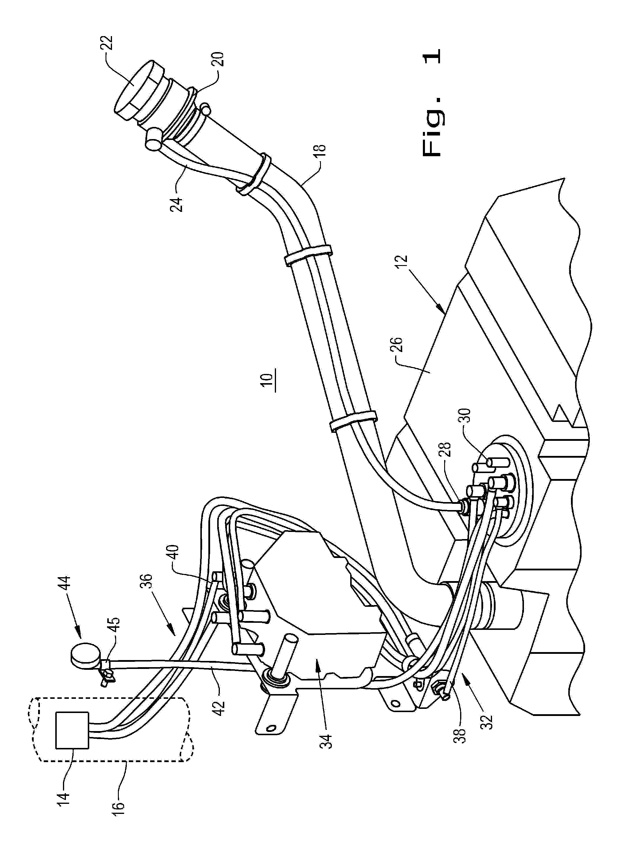
[0019]Referring now to the drawings, and more particularly to FIG. 1, there is shown a DEF delivery system 10 including a storage tank 12 for DEF fluid for delivery to a nozzle 14 located in the exhaust stream 16 of a work machine which is not shown to enable a better understanding of the present invention. Typically, engines for work machines are compression ignition, or diesels because of their torque capacity, durability and fuel economy.

[0020]Preferably the work machine is an agricultural combine which traverses a field containing crops and harvests them for collection and delivery to market. As stated above, EPA emission regulations applied to on-highway vehicles are being phased in to the off-highway field.

[0021]The DEF delivered to nozzle 14 in the exhaust system 16 causes a chemical reaction with selective catalytic reduction (SCR) to achieve reductions in nitrous oxides and meet the EPA limitation. A discussion of the details of this process is not included to simplify the ...


PUM


Abstract

A diesel exhaust fluid (DEF) delivery system includes a tank for DEF, usually a urea aqueous solution, and a pump receiving the DEF from the tank for pressurization and delivery through a nozzle to the exhaust system of a work machine. A breather assembly is provided for the DEF tank and includes a housing having an inlet for ambient air and a particle filter adjacent the inlet for filtering particles. A hydrophobic membrane is interposed between the particle filter and an outlet leading to the tank for preventing outflow of DEF vapor and condensate.

Description


Claims


Application Information

Patent Timeline
Owner BLUE LEAF I P
Why Eureka
Try Eureka