Cooling device for internal combustion engine

a technology for internal combustion engines and cooling devices, which is applied in the direction of machines/engines, process and machine control, instruments, etc., can solve problems such as possible erroneous determinations, and achieve the effect of suppressing erroneous determinations

Inactive Publication Date: 2015-06-04
TOYOTA JIDOSHA KK
View PDF0 Cites 8 Cited by
  • Summary
  • Abstract
  • Description
  • Claims
  • Application Information

AI Technical Summary

Benefits of technology

[0008]The present invention was made to solve the problem described above, and its object is to suppress erroneous determination in a failure diagnosis for a thermostat valve provided in a cooling device for an internal combustion engine.

Problems solved by technology

When the engine is started in such a situation, and a failure diagnosis for the thermostat valve is executed, erroneous determination is possibly made in the failure diagnosis due to the reversed relationship between the temperature of the circulating coolant water and the temperature of the coolant water remaining in the radiator circulation passage.

Method used


Image

  • Cooling device for internal combustion engine
  • Cooling device for internal combustion engine
  • Cooling device for internal combustion engine

Examples


modified example 1

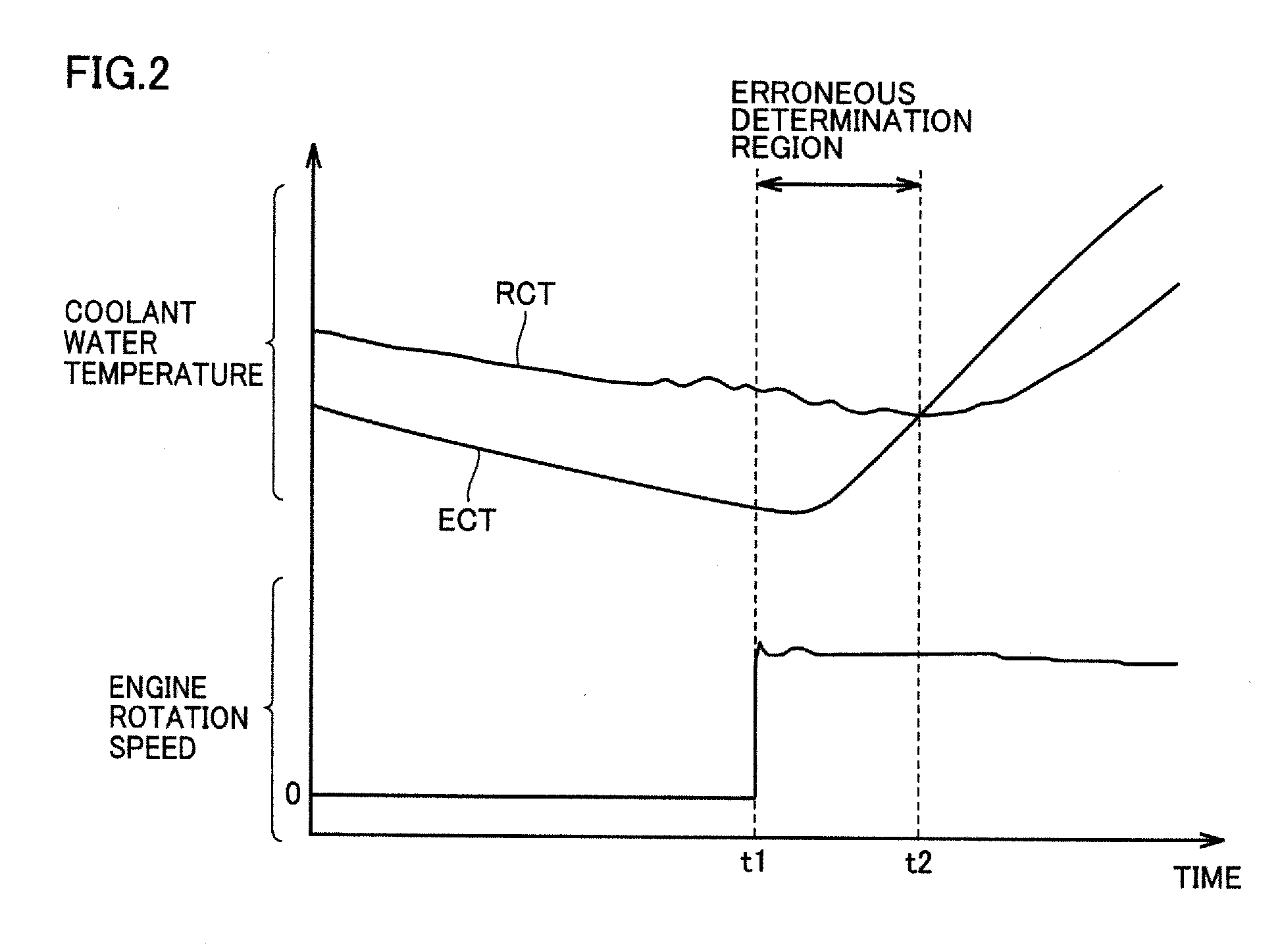
[0077]In the embodiment described above, starting of the thermostat valve failure diagnosis process after starting of the engine (the diagnosis precondition is met) is delayed based on the rise quantity (ΔECT) of the engine coolant water temperature (ECT detection value) after starting of engine 20. In place of water temperature rise quantity ΔECT, an integrated amount of the intake air volume into engine 20 from starting of engine 20 may be used. This is because the integrated intake air volume from starting of engine 20 may represent a tendency of the rise in temperatures of engine 20 and the coolant water.

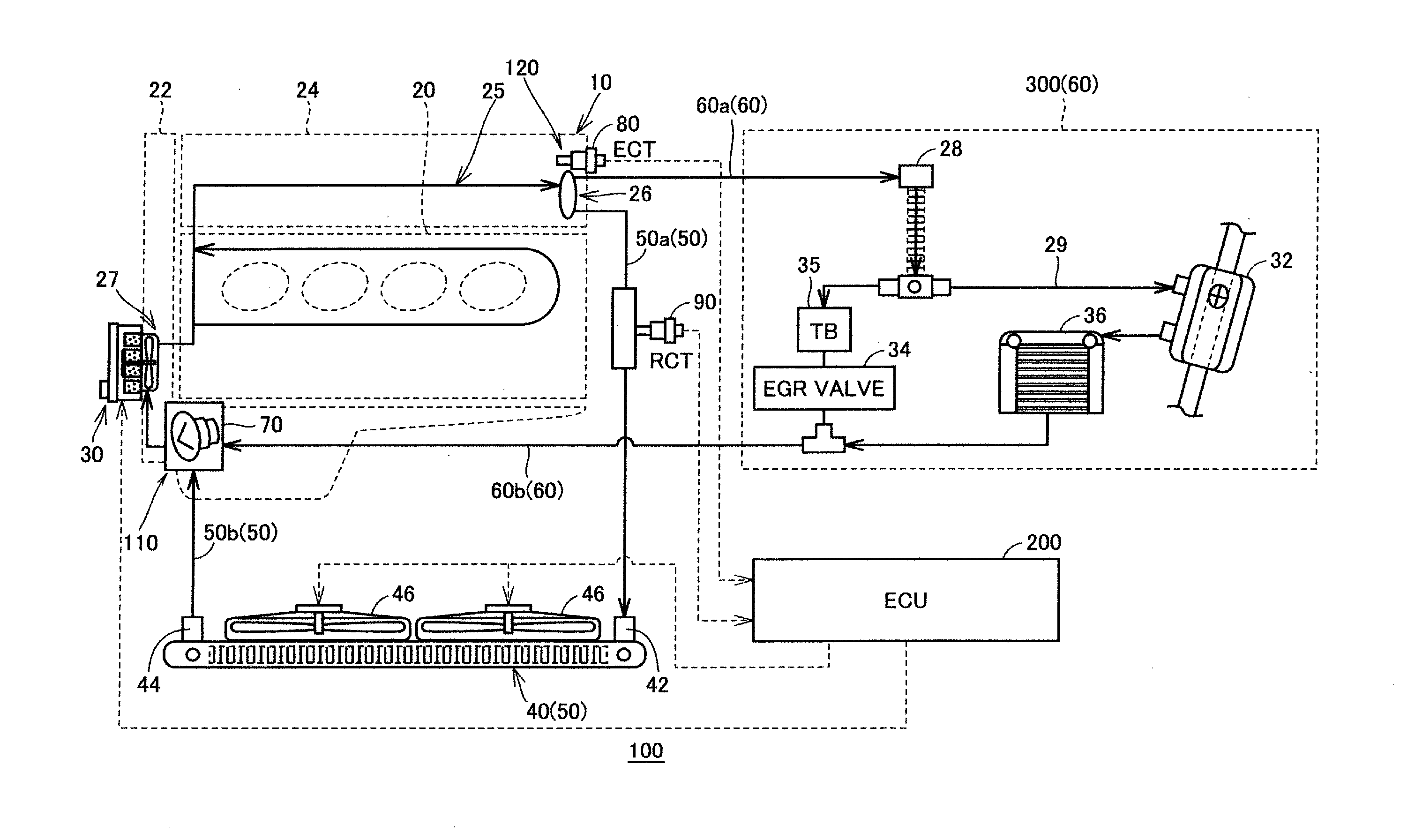
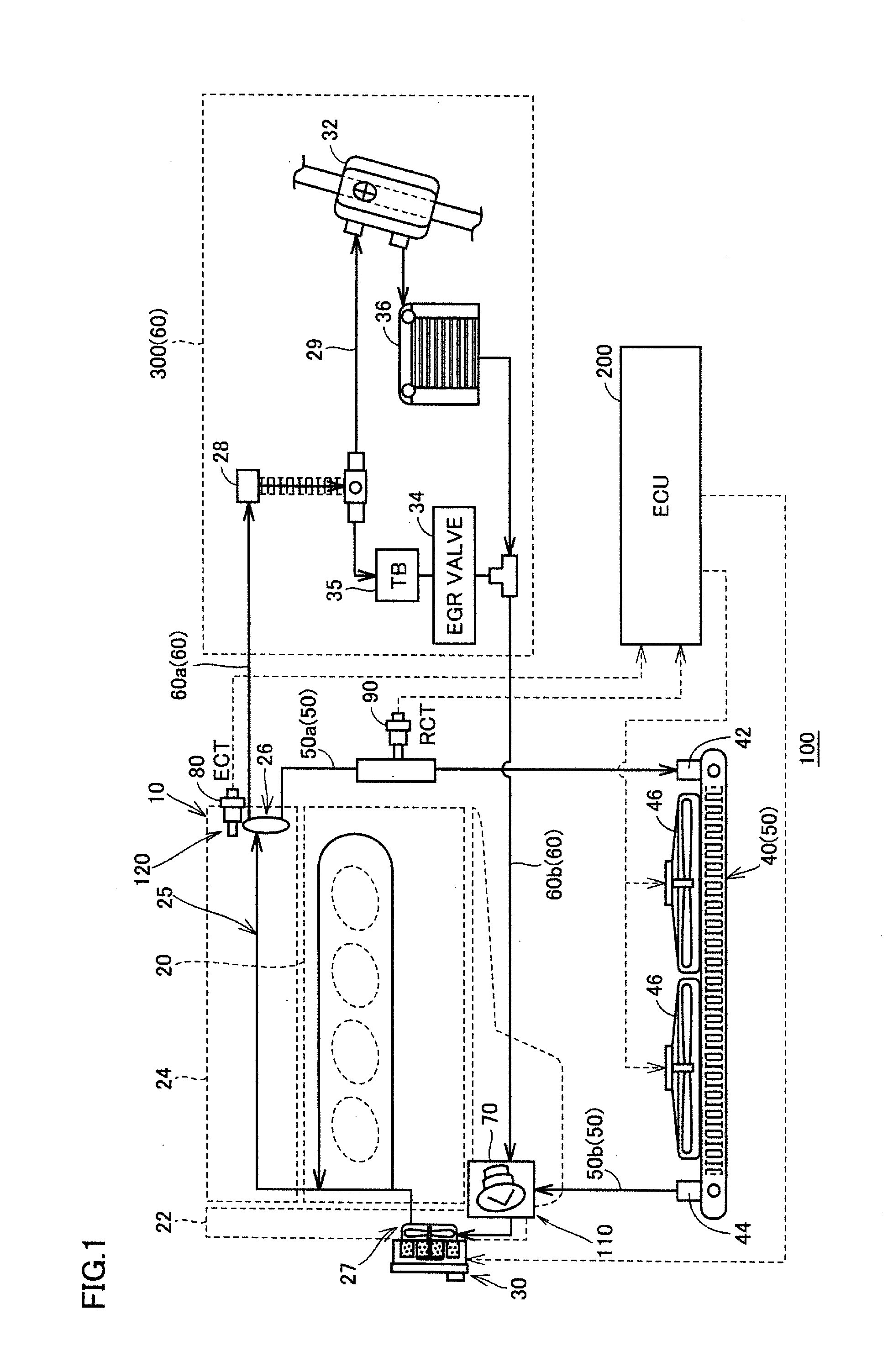
[0078]The overall configuration of the vehicle in this Modified Example 1 is the same as vehicle 100 shown in FIG. 1. Moreover, the procedures of the overall process of the thermostat valve failure diagnosis executed by ECU 200 of this Modified Example 1 is the same as the process procedures shown in FIG. 3.

[0079]FIG. 5 is a flowchart representing process procedures of the diagn...

modified example 2

[0084]While starting of the thermostat valve failure diagnosis from starting of engine 20 (the diagnosis precondition is met) is delayed based on the integrated intake air volume from starting of engine 20 in Modified Example 1 described above, time from starting of engine 20 can be measured to use an elapsed time after starting of the engine. Accordingly, the process of capturing a detection signal of a sensor and the calculation process are not required, so that the process of ECU 200 is simplified. Moreover, starting of the failure diagnosis can be adjusted without being affected by an abnormality of the sensor and a measurement accuracy.

[0085]The overall configuration of the vehicle in this Modified Example 2 is the same as that of vehicle 100 shown in FIG. 1. Moreover, the procedures of the overall process of the thermostat valve failure diagnosis executed by ECU 200 in this Modified Example 2 are the same as the process procedures shown in FIG. 3.

[0086]FIG. 6 is a flowchart re...


PUM


Abstract

An ECU performs a failure diagnosis for a thermostat valve after starting of an engine based on an output of an engine-side coolant water temperature sensor and an output of a radiator-side coolant water temperature sensor. When an electric pump operates in accordance with a heating request or the like of an air-conditioning device during stopping of the engine, the thermostat valve attains a closed state. When the electric pump operates during stopping of the engine before the current starting of the engine, starting of the failure diagnosis performed after starting of the engine is delayed as compared to the case where the electric pump does not operate during stopping of the engine. Consequently, erroneous determination can be suppressed in the failure diagnosis for the thermostat valve.

Description

[0001]This nonprovisional application is based on Japanese Patent Application No. 2013-250213 filed on Dec. 3, 2013 with the Japan Patent Office, the entire contents of which are hereby incorporated by reference.BACKGROUND OF THE INVENTION[0002]1. Field of the Invention[0003]The present invention relates to a cooling device for an internal combustion engine, and particularly to a technique of diagnosing a failure of a thermostat valve provided in a cooling device for an internal combustion engine.[0004]2. Description of the Background Art[0005]Japanese Patent Laying-Open No. 2010-196587 discloses an abnormality detecting device for detecting an abnormality of a thermostat valve provided in an engine cooling system of a hybrid vehicle capable of performing EV traveling of stopping an engine and traveling with a drive force of a motor. An increase in the EV traveling reduces an opportunity to operate an engine and in turn reduces an opportunity to detect an abnormality of a thermostat...

Claims


Application Information

Patent Timeline
Patent Type & Authority Applications(United States)
IPC IPC(8): F01P7/16F01P3/00
CPCF01P3/00F01P7/16F01P7/165F01P2025/32F01P2025/34F01P2060/08F01P2060/18
Inventor ANDO, IKUOSUGIMOTO, HITOKISASAKI, TOSHITAKEODA, YOSHIHISAKIMURA, KENJI
Owner TOYOTA JIDOSHA KK
Why Eureka
Try Eureka