LCD backlight driving circuit and liquid crystal device

a driving circuit and backlight technology, applied in static indicating devices, electrical appliances, instruments, etc., can solve the problems of low lighting efficiency, low color restoration, high discharging voltage, etc., and achieve the effect of increasing the feedback voltage, increasing the current within the led unit, and reducing the feedback voltag

Active Publication Date: 2015-05-28
SHENZHEN CHINA STAR OPTOELECTRONICS TECH CO LTD
View PDF2 Cites 8 Cited by
  • Summary
  • Abstract
  • Description
  • Claims
  • Application Information

AI Technical Summary

Benefits of technology

[0016]In view of the above, the driving module receives the feedback voltage generated by the feedback voltage module to adjust the current within the LED unit. In addition, the current within the LED unit is also precisely adjusted by the detecting module and the adjusting module. Specifically, one reference driving signals is configured within the detecting module. When detecting the current within the LED unit is smaller than the reference driving signals, the first adjusting signals are generated. The adjusting module increases the feedback voltage according to the first adjusting signals so as to increase the current within the LED unit. When detecting the current within the LED unit is larger than the reference driving signals, the second adjusting signals are generated. The adjusting module decreases the feedback voltage according to the second adjusting signals so as to decrease the current within the LED unit. In this way, not only the current precision within the LED unit is enhanced, but also the light source is kept stable. Also, the life cycle of the LED units is also increased.

Problems solved by technology

However, LEDs have now been adopted as backlight sources for the reason that the CCFLs have the disadvantages, such as low color restoration, low lighting efficiency, high discharging voltage, bad discharging characteristics at low temperature, and long heating time to achieve stable gray level.
As such, the precision of the driving current is also affected.

Method used


Image

  • LCD backlight driving circuit and liquid crystal device
  • LCD backlight driving circuit and liquid crystal device
  • LCD backlight driving circuit and liquid crystal device

Examples


Embodiment Construction

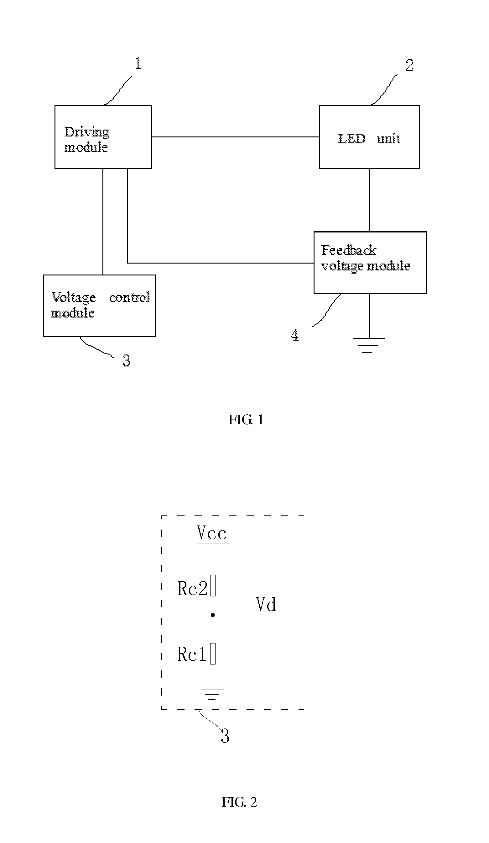
[0024]As stated above, the object of the claimed invention is to provide a LED backlight driving circuit for enhancing the current precision within the LED unit. The LED backlight driving circuit includes a driving module, a detecting module, and an adjusting module. The driving module is for receiving a control voltage generated by a voltage control module, receiving a feedback voltage generated by a feedback voltage module, and generating driving signals to a LED unit. The detecting module is for generating adjusting signals for the adjusting module 6 according to a detected value of the driving signals. The adjusting module is for controlling the feedback voltage according to the adjusting signals generated by the detecting module so as to adjust the driving signals. In this way, not only the current precision within the LED unit is enhanced, but also the light source is kept stable. Also, the life cycle of the LED units is also increased.

[0025]Embodiments of the invention will n...


PUM

PropertyMeasurementUnit
resistanceaaaaaaaaaa
voltageaaaaaaaaaa
feedback voltageaaaaaaaaaa

Abstract

A LED backlight driving circuit is disclosed. The LED backlight driving circuit includes a driving module, a detecting module, and an adjusting module. The driving module receives a control voltage generated by a voltage control module, receives a feedback voltage generated by a feedback voltage module, and generates driving signals to a LED unit. The detecting module generates adjusting signals for the adjusting module according to a detected value of the driving signals. The adjusting module controls the feedback voltage according to the adjusting signals generated by the detecting module so as to adjust the driving signals. In this way, not only the current precision within the LED unit is enhanced, but also the light source is kept stable. Also, the life cycle of the LED units is also increased. In addition, a LED backlight driving circuit includes the above LED backlight driving circuit is also disclosed.

Description

BACKGROUND OF THE INVENTION[0001]1. Field of the Invention[0002]The present disclosure relates to LED backlight driving circuit technology, and more particularly to a LED backlight driving circuit capable of precisely adjusting the current of LED units, and the liquid crystal device with the same.[0003]2. Discussion of the Related Art[0004]With the technical evolution, the backlight technology for the LCDs has been developed. In the past, CCFLs are adopted as backlight sources. However, LEDs have now been adopted as backlight sources for the reason that the CCFLs have the disadvantages, such as low color restoration, low lighting efficiency, high discharging voltage, bad discharging characteristics at low temperature, and long heating time to achieve stable gray level. Generally, the LED backlight source is arranged opposite to the liquid crystal panel so as to provide the light source to the liquid crystal panel. The LED backlight source includes at least one LED string having a pl...

Claims


Application Information

Patent Timeline
Patent Type & Authority Applications(United States)
IPC IPC(8): G09G3/34H05B33/08G02F1/1335H05B44/00
CPCG09G3/3426G02F2001/133612H05B33/0803G02F1/133603G09G3/3406H05B45/38H05B45/30G02F1/133612
Inventor ZHANG, XIANMING
Owner SHENZHEN CHINA STAR OPTOELECTRONICS TECH CO LTD
Why Eureka
Try Eureka