Piezoelectric actuator module and MEMS sensor having the same
a technology of actuator module and mems sensor, which is applied in the direction of instruments, specific gravity measurement, turn-sensitive devices, etc., can solve the problems of degrading productivity and difficult piezoelectric material poling process, and achieve the effect of high performan
- Summary
- Abstract
- Description
- Claims
- Application Information
AI Technical Summary
Benefits of technology
Problems solved by technology
Method used
Image


Examples
first embodiment
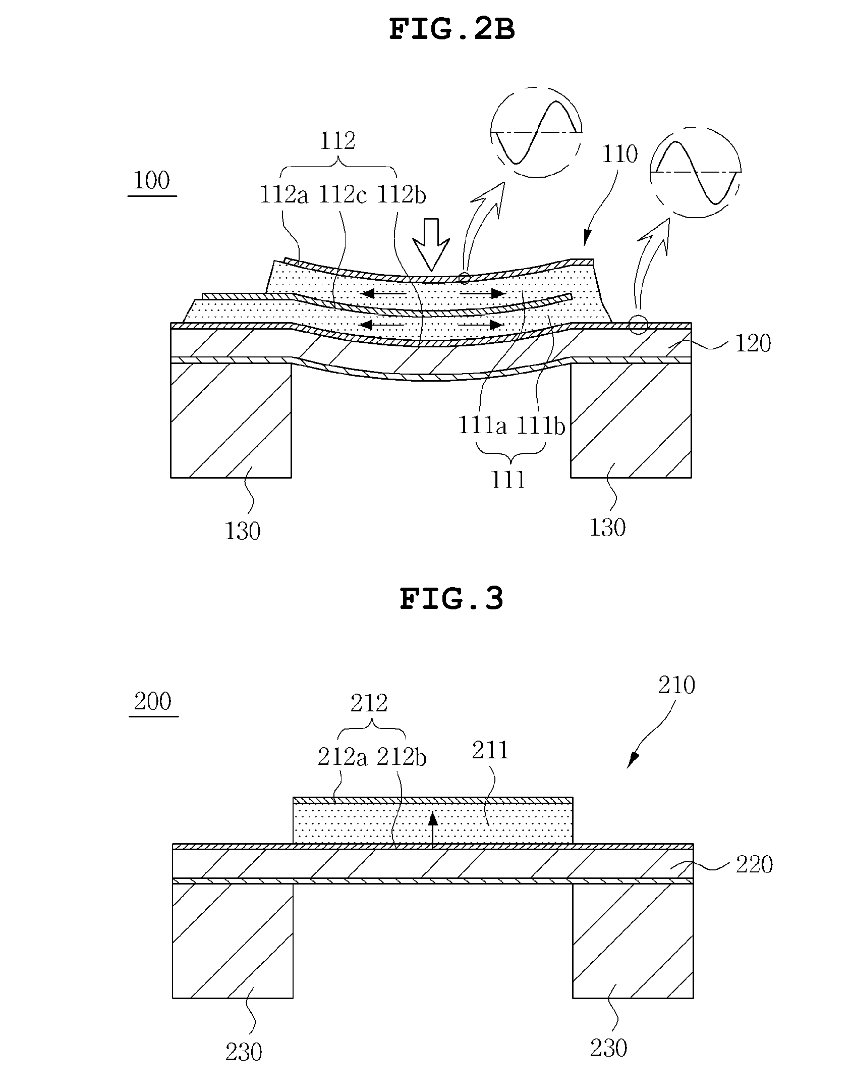
[0045]FIG. 1 is a diagram schematically showing a piezoelectric actuator module according to the invention. As shown, the piezoelectric actuator module 100 includes a multilayer part 110, a support layer 120 and support parts 130.
[0046]According to an embodiment, the multilayer part 110 is disposed on the support layer 120, and the support layer 120 is displaceably supported by the support parts 130. The multilayer part 110 receives voltages having the phase difference and contracts or expands to thereby provide vibration force. To this end, the multilayer part 110 includes a multilayer piezoelectric material part 111 and an electrode part 112.
[0047]According to an embodiment, the multilayer piezoelectric material part 111 is poled in the same direction and expands or contracts in the same direction.
[0048]According to an embodiment, the piezoelectric material part 111 includes a first piezoelectric material 111a and a second piezoelectric material 111b, and the first piezoelectric m...
second embodiment
[0066]FIG. 3 is a diagram schematically showing a piezoelectric actuator module according to the invention. As shown in FIG. 3, the piezoelectric actuator module 200 includes a multilayer part 210, a support layer 220 and support parts 230.
[0067]Specifically, the multilayer part 210 is disposed on the support layer 220, and the support layer 220 is displaceably supported by the support parts 230. The multilayer part 210 receives voltages out of phase and contracts or expands to thereby provide vibration force. To this end, the multilayer part 211 includes a piezoelectric material 211 and a multilayer electrode part 212.
[0068]Although the specific poling direction of the piezoelectric material 211 is indicated by the arrows in FIG. 3 for mere illustration, the poling direction is irrelevant to implementing a piezoelectric actuator module according to the second embodiment of the invention.
[0069]According to an embodiment, the multilayer electrode part 212 includes a first electrode 2...
third embodiment
[0087]FIG. 5 is a diagram schematically showing a piezoelectric actuator module according to the invention. As shown in FIG. 5, the piezoelectric actuator module 300 includes a multilayer part 310, a support layer 320 and support parts 330.
[0088]According to an embodiment, the multilayer part 310 is disposed on the support layer 320, and the support layer 320 is displaceably supported by the support parts 330.
[0089]According to an embodiment, the multilayer part 310 applies voltages having the phase difference of 180 degree to connected electrodes and a not-connected electrode so that piezoelectric materials contract or expand to thereby provide vibration force. To this end, the multilayer part 310 includes a multilayer piezoelectric material part 311 and an electrode part 312.
[0090]According to an embodiment, the multilayer piezoelectric material part 311 is poled in the opposite directions and expands or contracts in the same direction.
[0091]According to an embodiment, the multila...
PUM
 Abstract
Description
Claims
Application Information
 - R&D
- Intellectual Property
- Life Sciences
- Materials
- Tech Scout
- Unparalleled Data Quality
- Higher Quality Content
- 60% Fewer Hallucinations
Browse by: Latest US Patents, China's latest patents, Technical Efficacy Thesaurus, Application Domain, Technology Topic, Popular Technical Reports.
© 2025 PatSnap. All rights reserved.Legal|Privacy policy|Modern Slavery Act Transparency Statement|Sitemap|About US| Contact US: help@patsnap.com