
Therapeutic isolation tank

a technology for isolation tanks and floatation chambers, which is applied in the field of therapeutic isolation tanks, can solve the problems of difficult to find a location within an existing residence or therapeutic facility to build a new floatation chamber, difficult to integrate the plumbing and electrical needs of the floatation chamber with the existing plumbing and electrical lines of the existing structure, and achieve the effect of enhancing the therapeutic

Inactive Publication Date: 2015-05-21
SAN JUAN PATENTS
View PDF11 Cites 14 Cited by
  • Summary
  • Abstract
  • Description
  • Claims
  • Application Information

AI Technical Summary

Benefits of technology

The invention is a lightweight and easy-to-transport and install float tank for therapeutic floatation therapy. The tank can be used both indoors and outdoors. It also includes a hydrotherapy generator that creates small bubbles in the water to enhance the therapeutic effect of the floatation session.

Problems solved by technology

The technical problem addressed in this patent is the need for an improved float tank that can be easily transported and installed in either an existing structure or an outdoor location, and that enhances the therapeutic effect of floatation therapy. The current built-in floatation chambers are expensive, difficult to locate, and require specialized plumbing and electrical lines. The present invention aims to provide a solution to these needs.

Method used


Image

  • Therapeutic isolation tank
  • Therapeutic isolation tank
  • Therapeutic isolation tank

Examples


Embodiment Construction

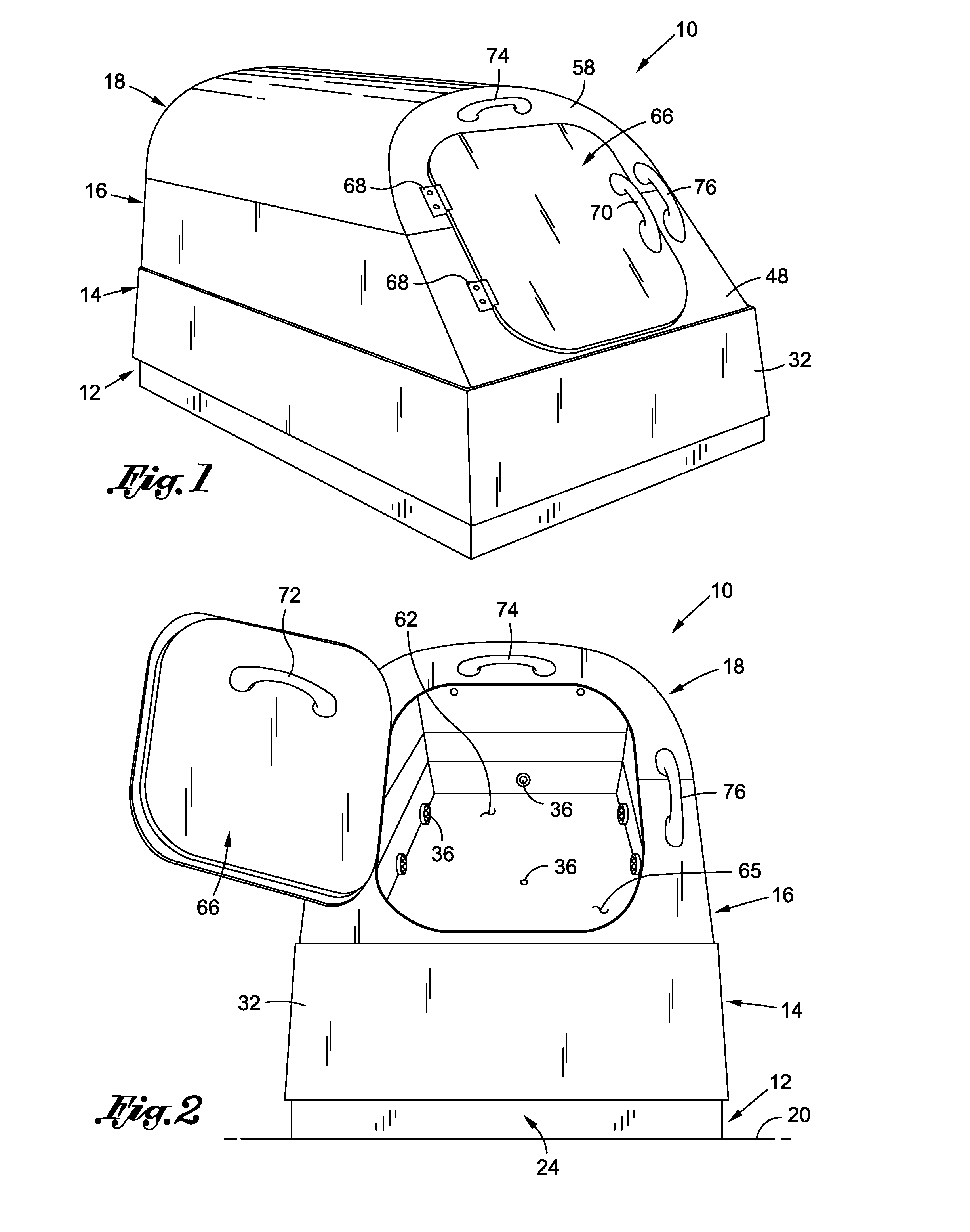
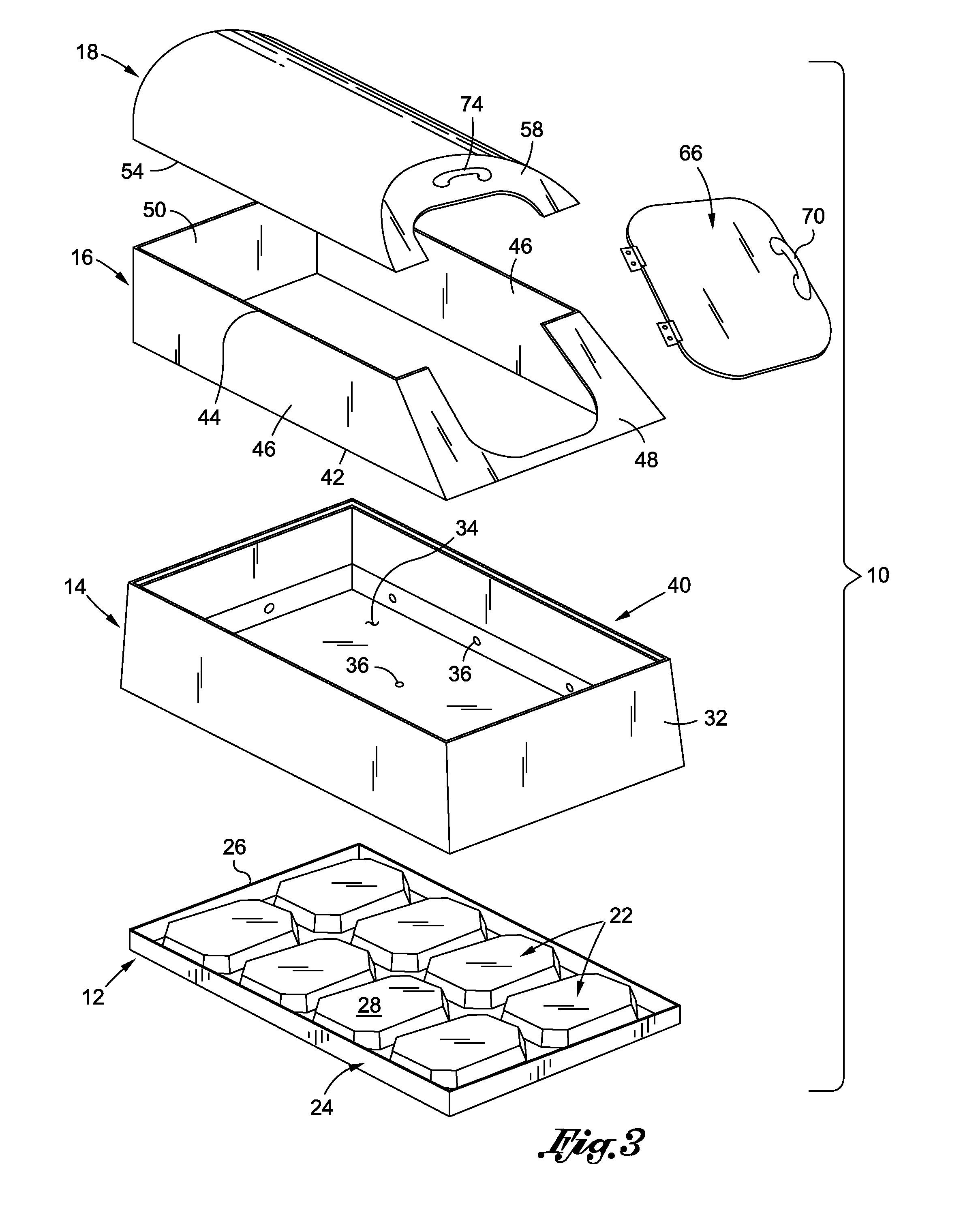
[0026]Referring now to the drawings, wherein the showings are for purposes of illustrating a preferred embodiment of the present invention only and not for purposes of limiting the same, there is depicted a therapeutic isolation float tank 10 constructed in accordance with a preferred embodiment of the present invention. The float tank 10 is specifically configured and adapted for easy transport, assembly and operation. Along these lines, the float tank 10 is divided into several discrete component sections which allow the float tank 10 to be carried and installed by a single user (in sections) in an existing structure, such as a residential home. Furthermore, the electrical components used in connection with the float tank 10 are preferably adapted to receive power from a standard household circuit. In this regard, various aspects of the float tank 10 are directed toward allowing the float tank 10 to be installed and used at a user's residence, either inside the residence or at a l...


PUM

PropertyMeasurementUnit
Diameteraaaaaaaaaa
Angleaaaaaaaaaa
Therapeuticaaaaaaaaaa

Abstract

A float tank for use in therapeutic floatation therapy. The float tank is specifically configured and adapted to be lightweight and formed in sections to allow a single individual to transport and install the float tank in both indoor and outdoor locations. The float tank may also include a pump which generates microbubbles within an Epsom Salt solution used for floatation therapy which may enhance the therapeutic effect achieved during a floatation therapy session.

Description


Claims


Application Information

Patent Timeline
Owner SAN JUAN PATENTS
Learn More