
Inclined conveyor for combine harvesters

a combine harvester and conveyor technology, applied in the direction of digger harvesters, agriculture tools and machines, agriculture, etc., can solve the problem of not reaching the yield point of rod material, and achieve the effect of reducing the load on the traction means, low weight of the carrier bars, and reducing the conveying speed

Inactive Publication Date: 2015-05-21
ARNOLD JAGER HLDG GMBH
View PDF6 Cites 5 Cited by
  • Summary
  • Abstract
  • Description
  • Claims
  • Application Information

AI Technical Summary

Benefits of technology

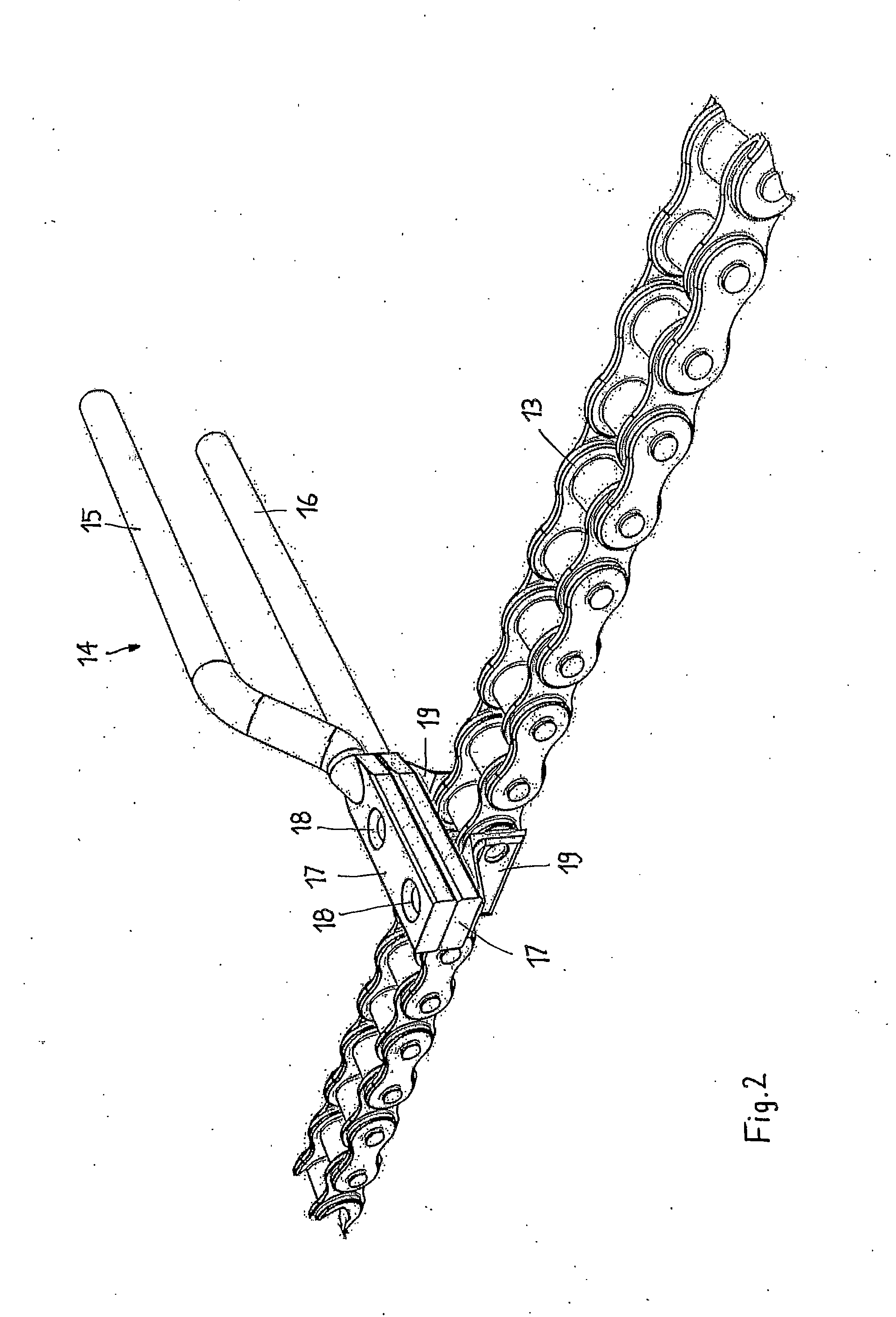
The present invention provides an inclined conveyor for a combine harvester with reduced load on the traction means due to a lower weight of the carrier bars and a lower conveying speed. The carrier bars are made up of at least two rods, situated one on top of the other, which have a circular cross section and are fastened to the traction means as individual rods. The rods are very flexible and can handle unfavorable load situations. The carrier bars have an increased entrainment effect on the harvested crop due to the small diameter of the rods and their superposed arrangement. The entrainment effect can be further increased even by providing the rods with a friction enhancing casing.

Problems solved by technology

As a result, the yield point of the rod material is not reached, even under unfavorable load situations (glass fiber principle).

Method used


Image

  • Inclined conveyor for combine harvesters
  • Inclined conveyor for combine harvesters
  • Inclined conveyor for combine harvesters

Examples


Embodiment Construction

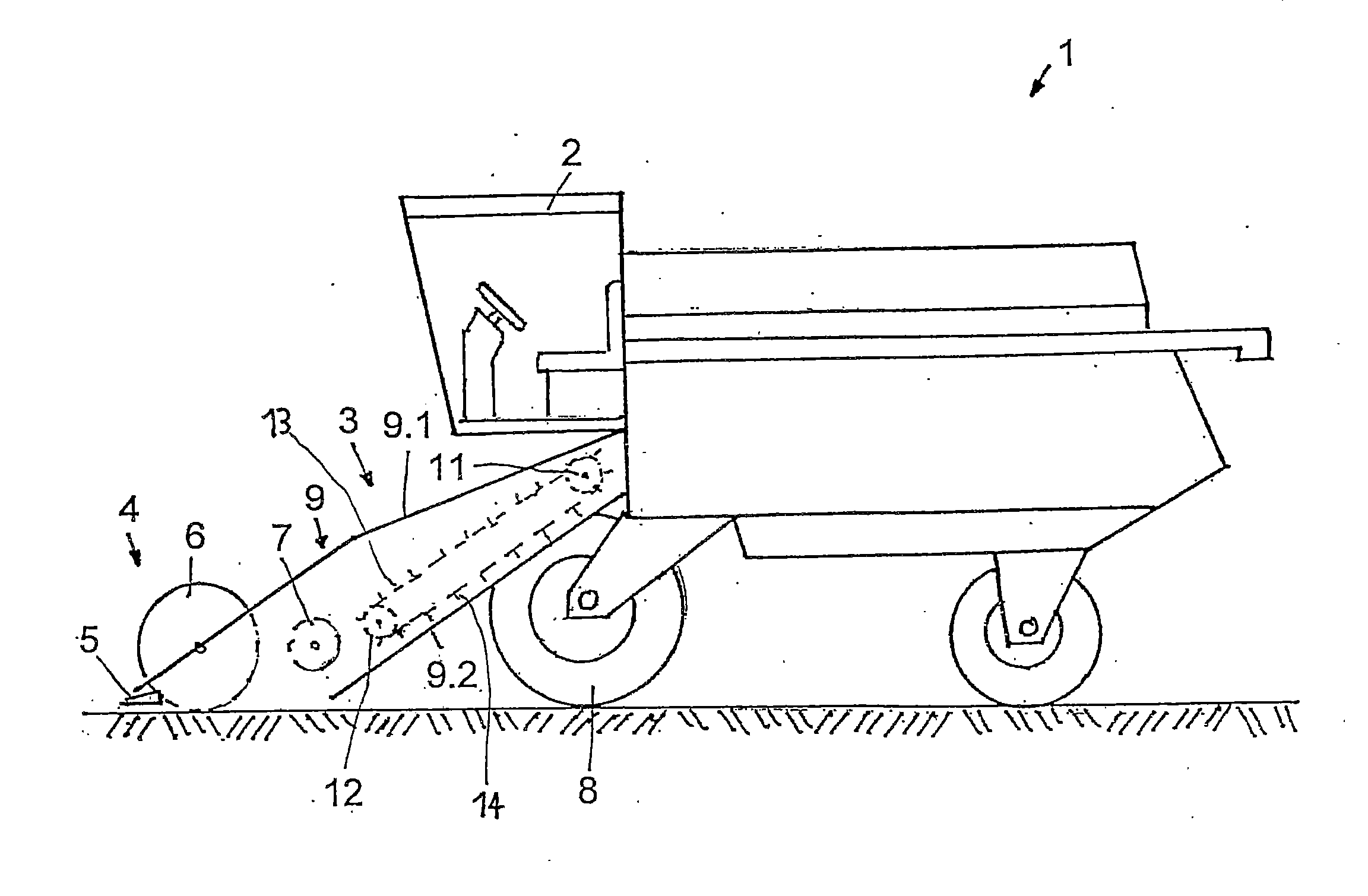
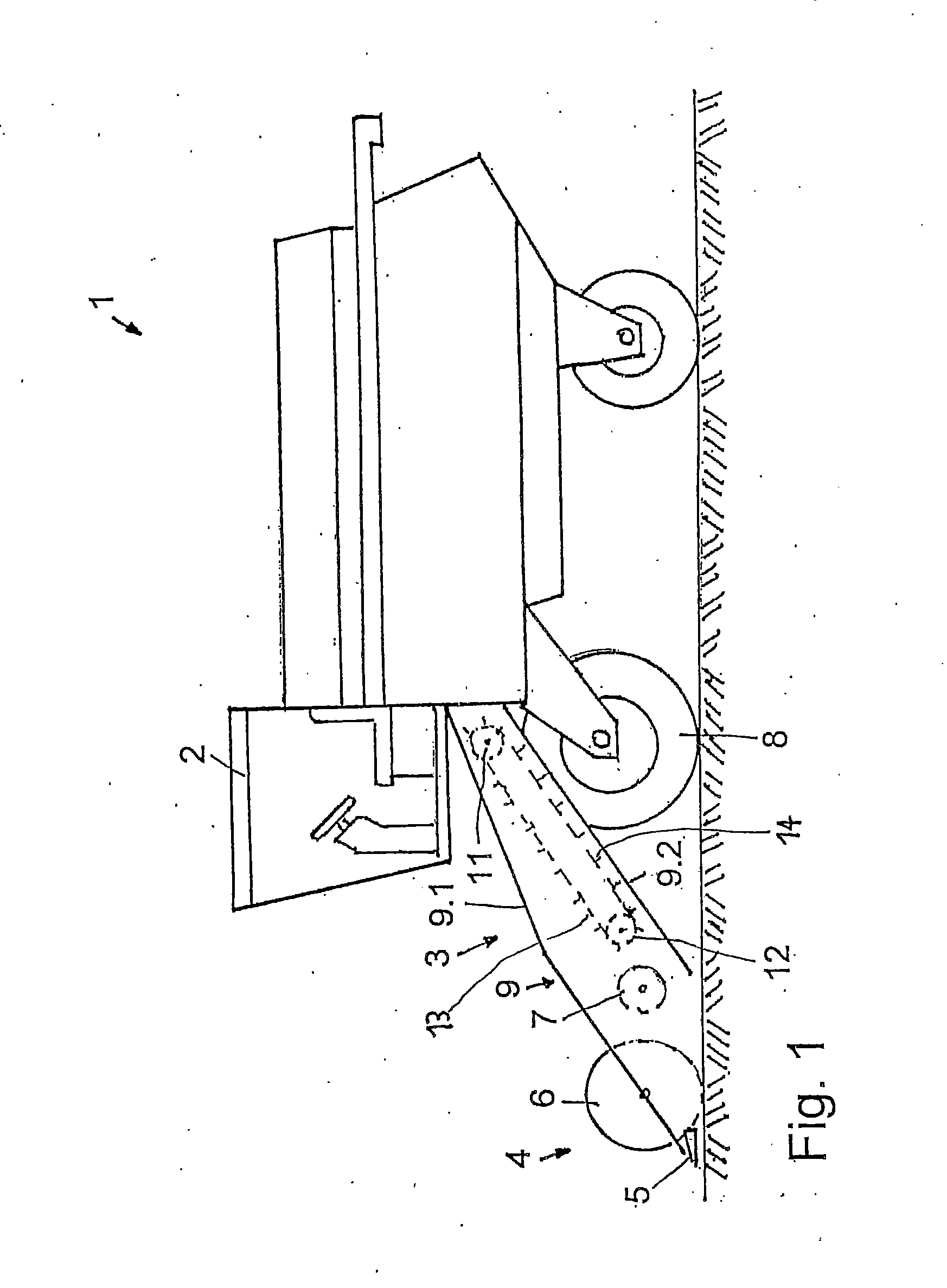
[0020]FIG. 1 shows a self-propelled combine harvester 1. Beneath the driver's cab 2, an inclined conveyor 3 extends downwardly toward the front. On its front end the inclined conveyor bears a cutter unit 4 made up of a cutter bar 5, a reel 6, and a cross auger 7. The cutter unit 4 is significantly wider than the combine harvester 1, and customarily extends transversely beyond the front drive wheels 8 of the combine harvester, while the inclined conveyor 3 is narrower. The harvested crop is cut by the cutter bar 5, collected by the reel 6, and supplied to the cross auger 7. The cross auger 7 compacts the harvested crop and conveys it toward the center, and supplies it to the inclined conveyor 3. The inclined conveyor is situated in a conveyor duct 9 having a top wall 9.1, a bottom wall 9.2, and two side walls. The inclined conveyor 3 feeds the harvested crop on the bottom wall 9.2 of the conveyor duct 9 to a threshing unit (not illustrated) of the combine harvester 1.

[0021]The inclin...


PUM


Abstract

An inclined conveyor for a combine harvester has at least two endless traction elements (drive elements) which extend in parallel to one another and which are interconnected by carrier bars. The carrier bars are situated transversely with respect to the conveying direction. The inclined conveyor is configured so that the load on the drive element is reduced due to the low weight of the carrier bars and a lower conveying speed. The carrier bars on the conveyor have at least two rods situated one on top of the other, have a circular cross section, and are fastened to the drive element as individual rods.

Description

RELATED APPLICATIONS[0001]This is a continuation of International PCT Application No. PCT / DE2013 / 100180, filed on May 16, 2013, which claims priority from Germany Application No. 10 2012 010 280.1, filed May 21, 2012, both of which are hereby incorporated by reference.FIELD OF THE INVENTION[0002]The present invention relates to an inclined conveyor for a combine harvester according to the preamble of claim 1.BACKGROUND OF THE INVENTION[0003]Combine harvesters are equipped with an attachment which has a reel for collecting the harvested crop, and a cross auger, situated downstream from the reel, which compacts the harvested crop and conveys it toward the center to an inclined conveyor. The inclined conveyor is situated in a duct, and conveys the harvested crop into a threshing device of the combine harvester.[0004]Inclined conveyors of this type for combine harvesters are well known in the prior art, for example from DE 1199039, U.S. Pat. No. 3,555,790, DE 4132246 A1, DE 4311054 C2, ...

Claims


Application Information

Patent Timeline
IPC IPC(8): A01D61/00A01F12/10
CPCA01D61/008A01F12/10B65G19/24
Inventor MULDER, JAN-HARMOORD, JOHANJÄGER, SEBASTIAN
Owner ARNOLD JAGER HLDG GMBH
Learn More