
Gas turbine engine ducting arrangement having discrete insert

a gas turbine engine and insert technology, applied in the direction of machines/engines, liquid fuel engines, lighting and heating apparatus, etc., can solve the problems of significant pressure differences (up to six atmospheres) and the resulting force acting on the exterior surface of the duct arrangemen

Inactive Publication Date: 2015-05-14
SIEMENS ENERGY INC
View PDF3 Cites 15 Cited by
  • Summary
  • Abstract
  • Description
  • Claims
  • Application Information

AI Technical Summary

Benefits of technology

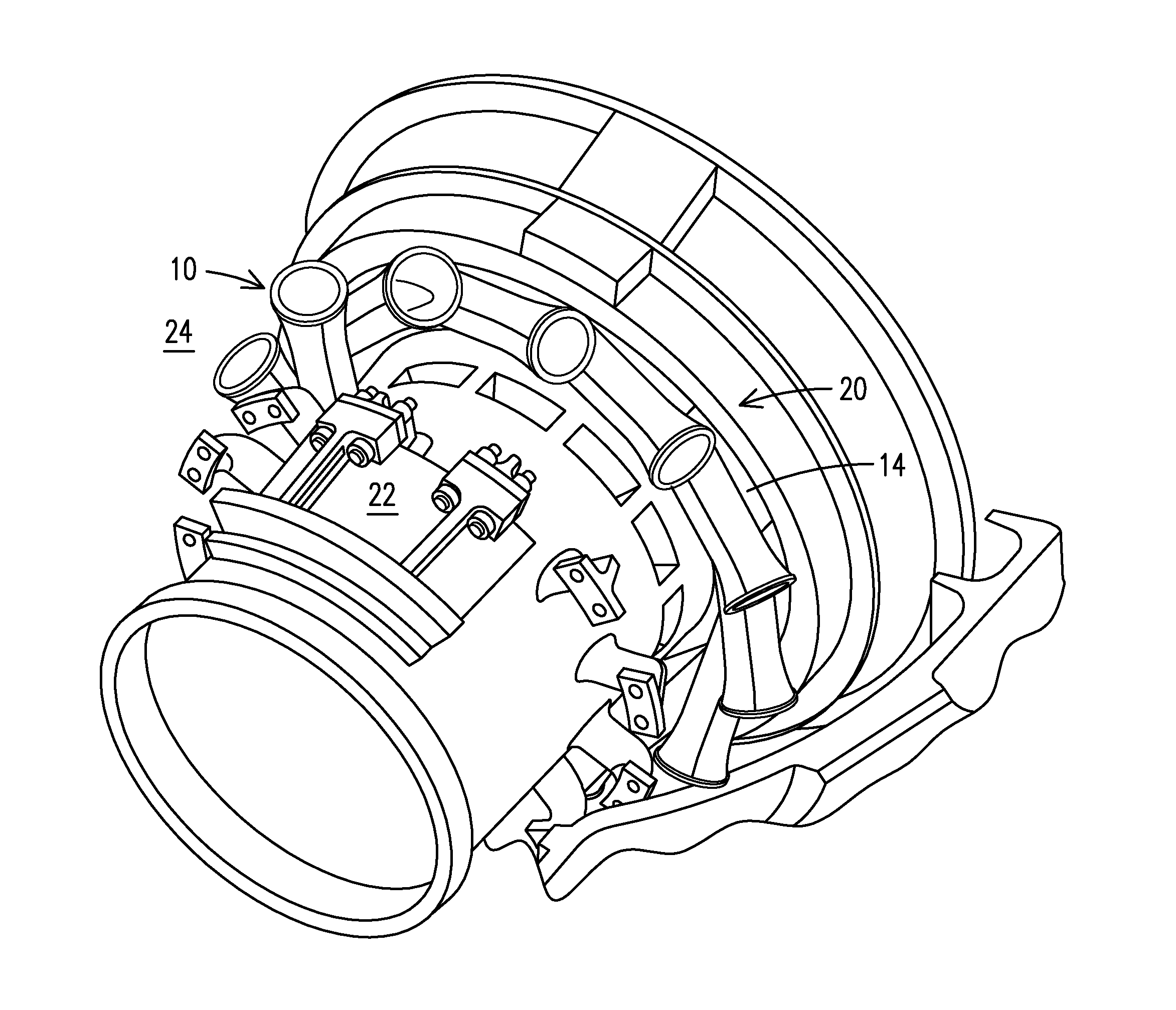
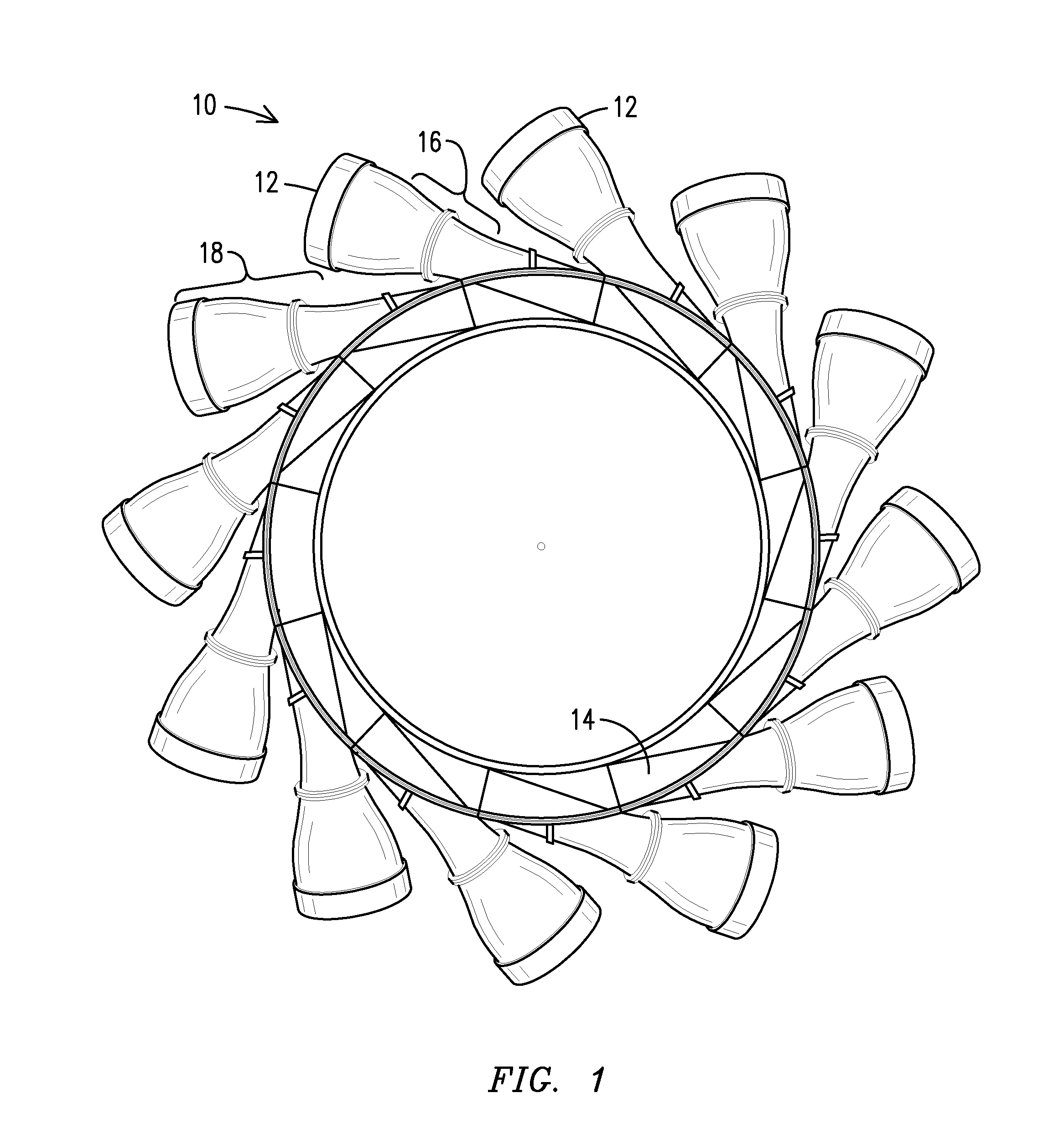
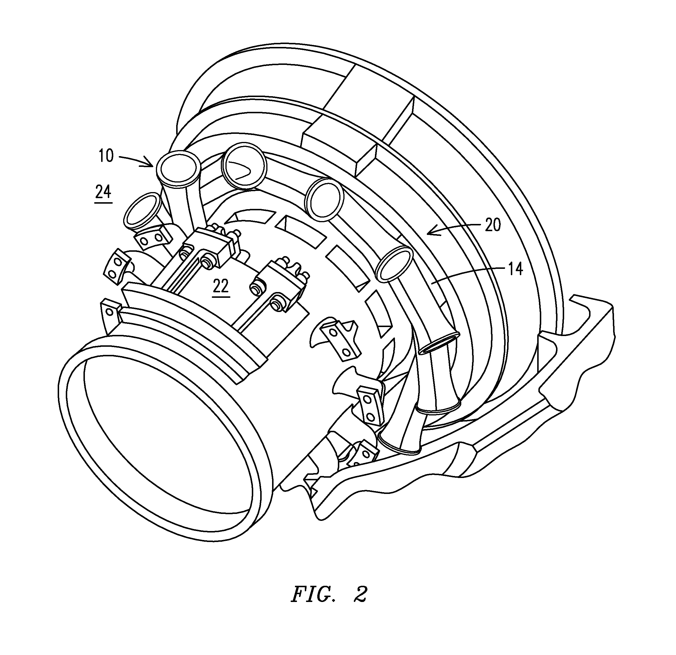
The present invention relates to a duct for a gas turbine engine that includes a discrete insert with a different mechanical property than the remainder of the duct. The duct is formed by bi-casting duct material around the insert. This arrangement reduces mechanical stresses and thermal stresses in the duct, allowing for the use of an insert with a different material that is better suited for the local region. The invention also proposes reducing the stresses at the region where the highest mechanical and thermal stresses are likely to occur, and thereby extending the service life of the duct.

Problems solved by technology

This results in significantly greater pressure differences (up to six atmospheres) and resulting forces acting on the exterior surface of the ducting arrangement.

Method used


Image

  • Gas turbine engine ducting arrangement having discrete insert
  • Gas turbine engine ducting arrangement having discrete insert
  • Gas turbine engine ducting arrangement having discrete insert

Examples


Embodiment Construction

[0013]The present inventors have recognized at least one form of deformation that may occur when using one exemplary embodiment of a ducting arrangement and have identified a region of the ducting arrangement likely to experience substantial mechanical stresses as a result of this deformation. The inventors have further recognized that this region of relatively great mechanical stress is also a region of relatively great thermal stress which compounds the problem.

[0014]To accommodate this localized region of high mechanical and thermal stresses, and thereby extend the service life of the ducting arrangement, the inventors have proposed an innovative arrangement that lowers the mechanical stresses in the area. This, in turn, permits the use of an insert having a material that is better suited thermally for the local region, and this reduces an amount of cooling air that is required for the local region which, in turn, increases engine efficiency. Reducing the stresses at this locatio...


PUM


Abstract

A ducting arrangement (10), including: a plurality of discrete ducts (18), each defining a flow path and configured to receive a flow of combustion gases from a respective combustor can, where the plurality of discrete ducts merge to form a common duct structure; and a throat insert (50) configured to define at least part of a junction of one of the discrete ducts and the common duct structure.

Description

STATEMENT REGARDING FEDERALLY SPONSORED DEVELOPMENT[0001]Development for this invention was supported in part by Contract No. DE-FC26-05NT42644, awarded by the United States Department of Energy. Accordingly, the United States Government may have certain rights in this invention.FIELD OF THE INVENTION[0002]The present invention relates to a combustion gas duct that includes a discrete insert having a different mechanical property than a remainder of the duct. The combustion gas duct may be formed by bi-casting duct material around the insert.BACKGROUND OF THE INVENTION[0003]Conventional can-annular gas turbine engines include a plurality of individual combustor cans, where each can is secured to a respective transition duct that directs combustion gases from the combustor can, and through inlet guide vanes to a respective portion of a turbine inlet annulus. Each flow of combustion gas remains discrete from the combustor until exiting the respective transition duct. In contrast, in c...

Claims


Application Information

Patent Timeline
IPC IPC(8): F01D9/02F23R3/46
CPCF23R3/46F01D9/023F05D2260/941F05D2270/114F23R3/425
Inventor MARRA, JOHN J.MORRISON, JAY A.CAMPBELL, ERNIE B.
Owner SIEMENS ENERGY INC
Learn More