
Light source apparatus and image projection apparatus

a technology of light source and image, which is applied in the direction of lighting and heating apparatus, instruments, optics, etc., can solve the problems of phosphor member becoming too high temperature, deteriorating light use efficiency, and affecting the life of the motor

Inactive Publication Date: 2015-05-14
RICOH KK
View PDF9 Cites 23 Cited by
  • Summary
  • Abstract
  • Description
  • Claims
  • Application Information

AI Technical Summary

Benefits of technology

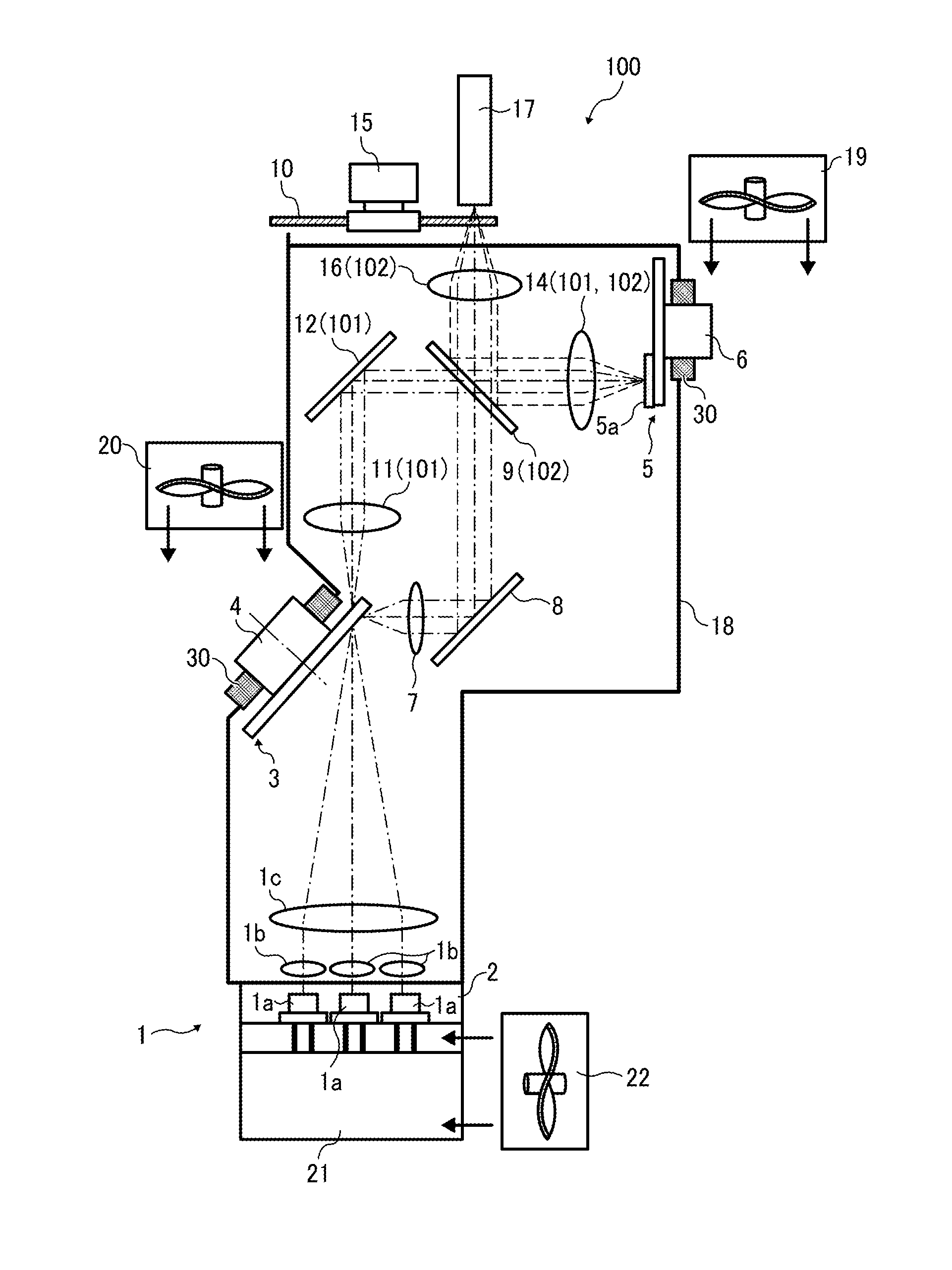
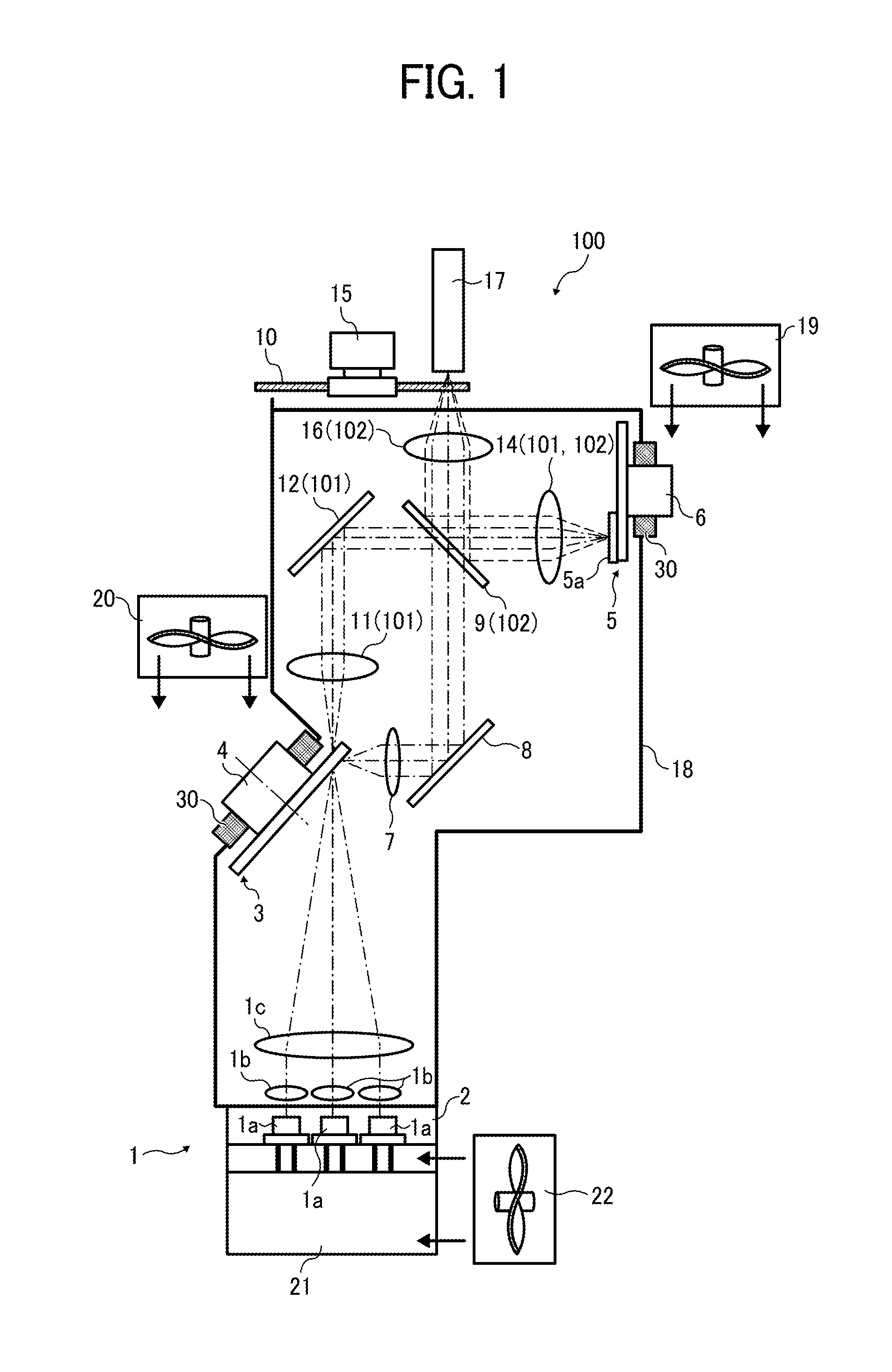
The invention is about a mechanism to prevent the parts used in a light source and image projection apparatus from getting too hot and getting dusty. This reduces the effects of heat and keeps the parts clean.

Problems solved by technology

The phosphor member becomes too high temperature by the heat generation caused by this light loss, and also by heat generation when the phosphor material converts wavelength of excitation light.
Further, if dust adheres on the phosphor member, light is absorbed or scattered by dust, with which light use efficiency deteriorates.
However, in this configuration, a motor that drives the phosphor member is disposed in the same space encasing the phosphor member, in which temperature increase of ambient air caused by heat generation of the phosphor member affects the motor, and lifetime of the motor may deteriorate.
The phosphor can be cooled by ambient air around the phosphor member in the closed space, but if ambient temperature increases over the time, abnormal temperature increase may occur to the motor, and lifetime of the motor may deteriorate.

Method used


Image

  • Light source apparatus and image projection apparatus
  • Light source apparatus and image projection apparatus
  • Light source apparatus and image projection apparatus

Examples


Embodiment Construction

[0022]A description is now given of exemplary embodiments of the present invention. It should be noted that although such terms as first, second, etc. may be used herein to describe various elements, components, regions, layers and / or sections, it should be understood that such elements, components, regions, layers and / or sections are not limited thereby because such terms are relative, that is, used only to distinguish one element, component, region, layer or section from another region, layer or section. Thus, for example, a first element, component, region, layer or section discussed below could be termed a second element, component, region, layer or section without departing from the teachings of the present invention.

[0023]In addition, it should be noted that the terminology used herein is for the purpose of describing particular embodiments only and is not intended to be limiting of the present invention. Thus, for example, as used herein, the singular forms “a”, “an” and “the...


PUM


Abstract

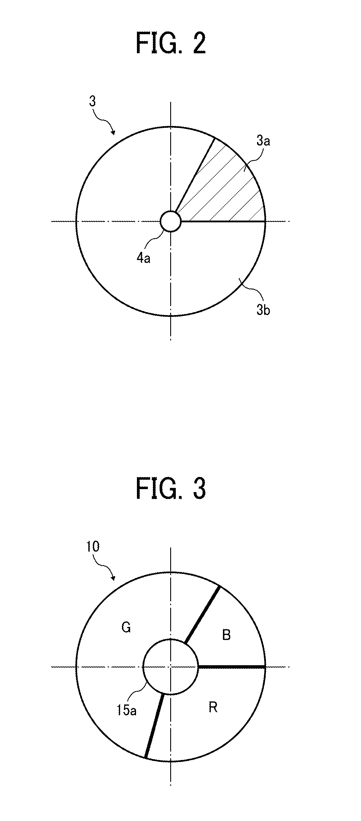
A light source apparatus includes a light source to emit excitation light; a phosphor as a rotatable wavelength convertor; a motor to drive the phosphor; an excitation light condensing optical system to condense the excitation light emitted from the light source onto the phosphor; and a casing having a closed space to encase the light source, the phosphor, and the excitation light condensing optical system, and at least a part of the motor while a remaining part of the motor being protruded to an external space of the casing.

Description

CROSS-REFERENCE TO RELATED APPLICATION[0001]This application claims priority pursuant to 35 U.S.C. §119(a) to Japanese Patent Application Nos. 2013-234322, filed on Nov. 12, 2013 in the Japan Patent Office, the disclosure of which are incorporated by reference herein in their entirety.BACKGROUND[0002]1. Technical Field[0003]The present invention relates to a light source apparatus, an image projection apparatus, and more particularly, to a mechanism for reducing affect of heat generated to parts used in a light source apparatus and an image projection apparatus, and preventing dust adhesion to the parts.[0004]2. Background Art[0005]Screen images of personal computers, video images, and image data stored in memory cards can be transmitted to image projection apparatuses known as projectors that can project images onto a screen. In the projector, light emitted from a light source is focused on a micro mirror display device known as a digital micro mirror device (DMD), or a liquid crys...

Claims


Application Information

Patent Timeline
Patent Type & Authority Applications(United States)
IPC IPC(8): F21V14/08G03B21/16G03B21/20
CPCF21V14/08G03B21/16G03B21/204G03B21/145G03B33/08H04N9/3114
Inventor NISHIMORI, TAKEHIROFUJITA, KAZUHIROMURAI, TOSHIHARUTAKAHASHI, TATSUYA
Owner RICOH KK
Learn More