Eureka AIR delivers breakthrough ideas for toughest innovation challenges, trusted by R&D personnel around the world.

Overcurrent relay and molded case circuit breaker with the same

a technology of overcurrent relay and circuit breaker, which is applied in the direction of circuit breaker, protective switch details, protective switch operating/release mechanisms, etc., can solve the problem of mccb operation off function in case of long-time limit against application standards

Active Publication Date: 2015-05-14
LSIS CO LTD
View PDF16 Cites 7 Cited by
  • Summary
  • Abstract
  • Description
  • Claims
  • Application Information

AI Technical Summary

Benefits of technology

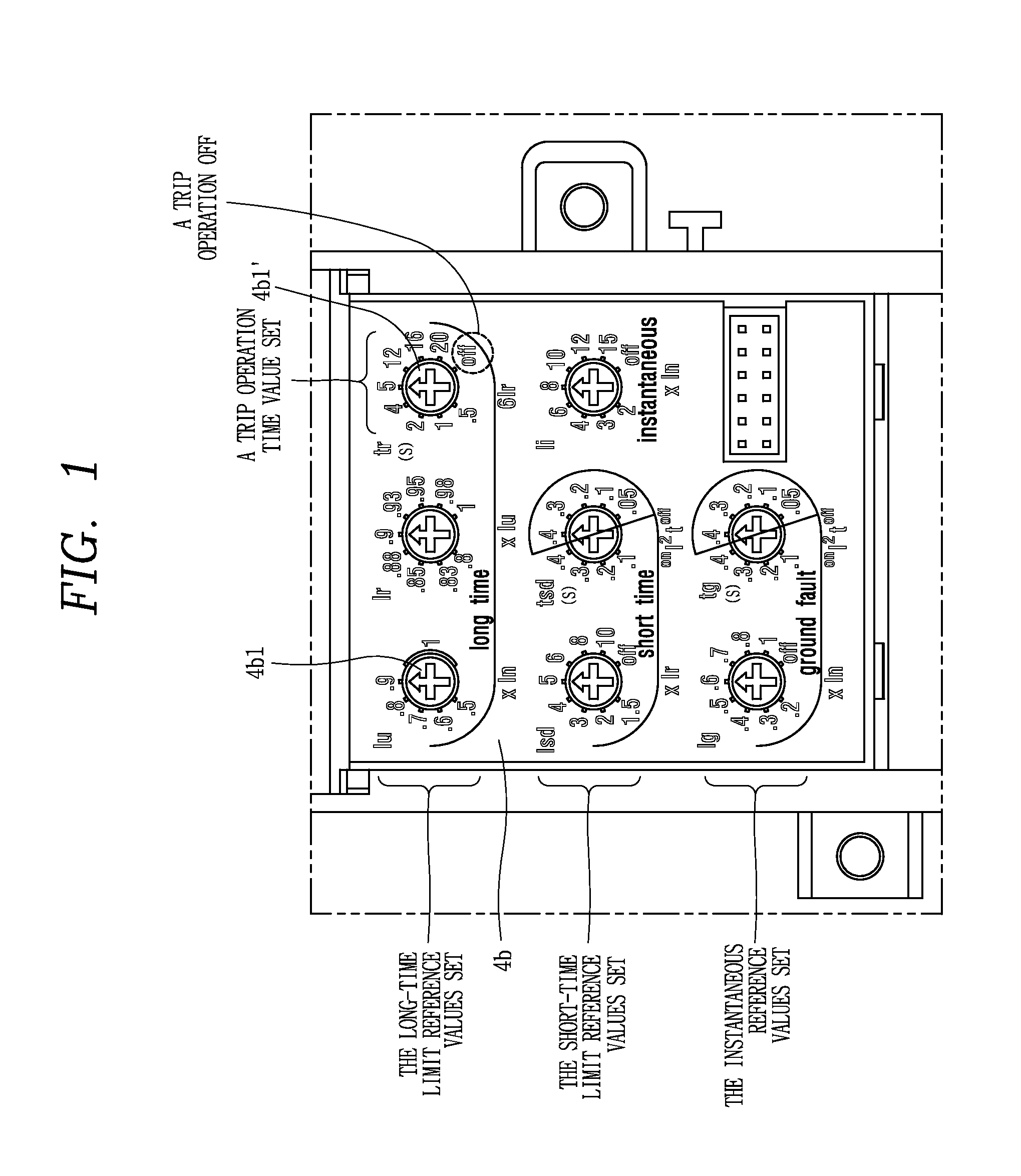
The present invention describes an overcurrent relay that has a dedicated setting knob or stop protrusion to limit a long-time limit trip operation OFF function. This allows for the same settings to be used for both an ACB and an MCCB using the same OCR program and PCB. The technical effect is that the relay provides more flexibility and versatility in setting the trip operation conditions, making it easier to use in different electrical systems.

Problems solved by technology

However, a trip operation OFF function of an MCCB in case of a long-time limit is against the application standards of Underwriters Laboratories Inc.

Method used


Image

  • Overcurrent relay and molded case circuit breaker with the same
  • Overcurrent relay and molded case circuit breaker with the same
  • Overcurrent relay and molded case circuit breaker with the same

Examples


first embodiment

[0153]In order to reduce a maximal rotation available range of the dedicated knob 115 according to the present disclosure, the stoppage protrusion 115d of the dedicated knob 115 may extend in the circumferential direction.

[0154]According to the first embodiment, the stop protrusion 112a corresponding to the dedicated knob 115 may have a shape, structure, and size identical to those of other stop protrusions 112a.

[0155]However, since the length of the stoppage protrusion 115d provided on the rotary plate 115a of the dedicated knob 115 in the circumferential direction is longer than the stoppage protrusion 116d provided on the rotary plate 116a of each of other setting knobs 116 in the circumferential direction, a rotation angle range of the dedicated knob 115 may be relatively reduced, compared to the other setting knobs 116.

[0156]According to the following equation, as the length of the stoppage protrusions 116d and 115d provided on the rotary plates 116a and 115a in the circumfere...

second embodiment

[0163]FIG. 11 is an internal perspective view illustrating a state in which setting knobs are installed within a case cover setting knobs according to the present disclosure.

[0164]An overcurrent relay 110 according to the second embodiment of the present disclosure may provide a dedicated stop protrusion 112b for preventing a trip operation OFF function.

[0165]The dedicated stop protrusion 112b may be any one of a plurality of stop protrusions provided within a case cover 112.

[0166]The dedicated stop protrusion 112b may be applied to correspond to the dedicated knob 115 positioned in the uppermost portion at the right among eight setting knobs 116 when the electronic circuit board is viewed from the front side.

[0167]The dedicated stop protrusion 112b may further extend, relative to the lengths of the other stop protrusions 112a, among the plurality of stop protrusions 112a, in the circumferential direction.

[0168]Among the setting knobs 116, the dedicated knob 115 for setting a long-t...


PUM


Abstract

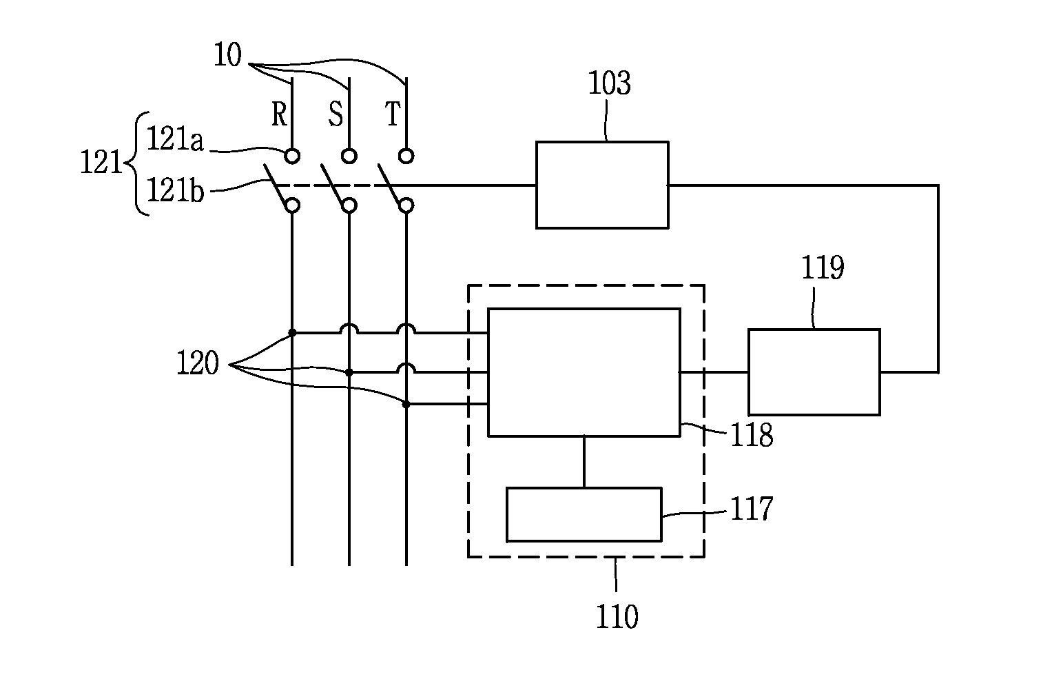
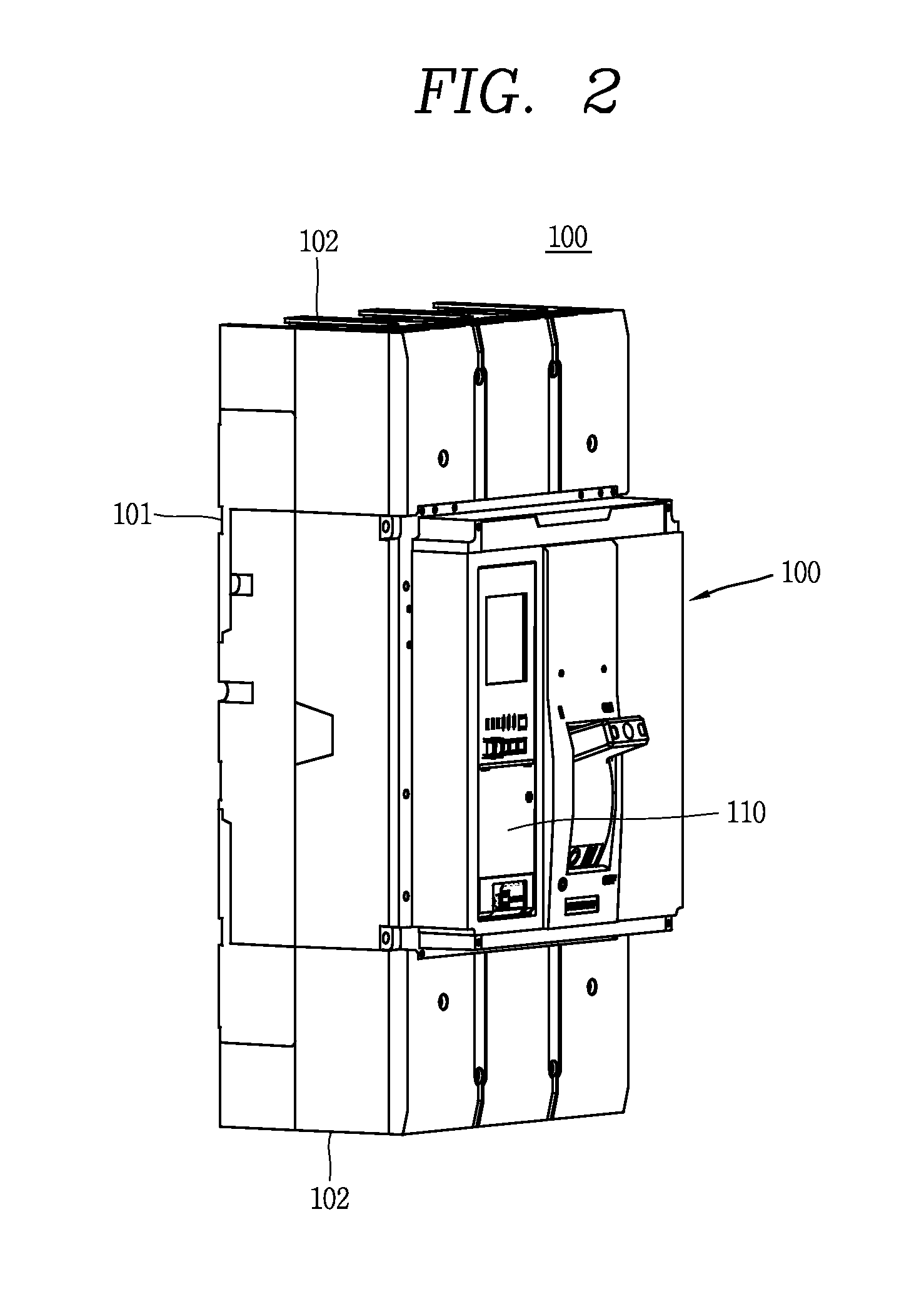
An overcurrent relay and a molded case circuit breaker (MCCB) including the same are provided. The MCCB includes: a switching mechanism unit; an overcurrent relay; a trip mechanism, wherein the overcurrent relay includes: a case body; a case cover coupled to the case body; a control unit installed within the case body and having an electronic circuit board; and a plurality of setting knobs disposed to be spaced apart from one another on the electronic circuit board, having an indication unit exposed to the outside to indicate a current reference value and a trip operation time marked on the case cover, respectively, and configured to be rotatable, respectively.

Description

CROSS-REFERENCE TO RELATED APPLICATION[0001]Pursuant to 35 U.S.C. §119(a), this application claims the benefit of earlier filing date and right of priority to Korean Patent Application No. 10-2013-0136453, filed on Nov. 11, 2013, the contents of which are hereby incorporated by reference herein in its entirety.BACKGROUND OF THE INVENTION[0002]1. Field of the Invention[0003]The present disclosure relates to an overcurrent relay applied to a molded case circuit breaker, or the like.[0004]2. Background of the Invention[0005]In general, a protecting relay is a device that monitors a state of an electric power system, and when an accident occurs, the protecting relay detects the accident and operates a breaker to quickly separate an accident section to minimize a section affected by the accident.[0006]Among protecting relays, an overcurrent relay is a protecting relay operating when an input current is equal to or greater than a pre-set value. Overcurrent relays have been used in various...

Claims


Application Information

Patent Timeline
Patent Type & Authority Applications(United States)
IPC IPC(8): H01H71/02H02H3/093
CPCH02H3/093H01H71/025H01H71/02H01H71/52H01H71/74
Inventor JANG, JUN YONG
Owner LSIS CO LTD
Why Eureka
Eureka Blog
Learn More