Lid body, package, electronic apparatus, moving object, and method for manufacturing package
a technology of electronic equipment and packaging, applied in the field of packaging, electronic equipment, moving objects, and manufacturing methods of packages, can solve problems such as sealing failur
- Summary
- Abstract
- Description
- Claims
- Application Information
AI Technical Summary
Benefits of technology
Problems solved by technology
Method used
Image
Examples
first embodiment
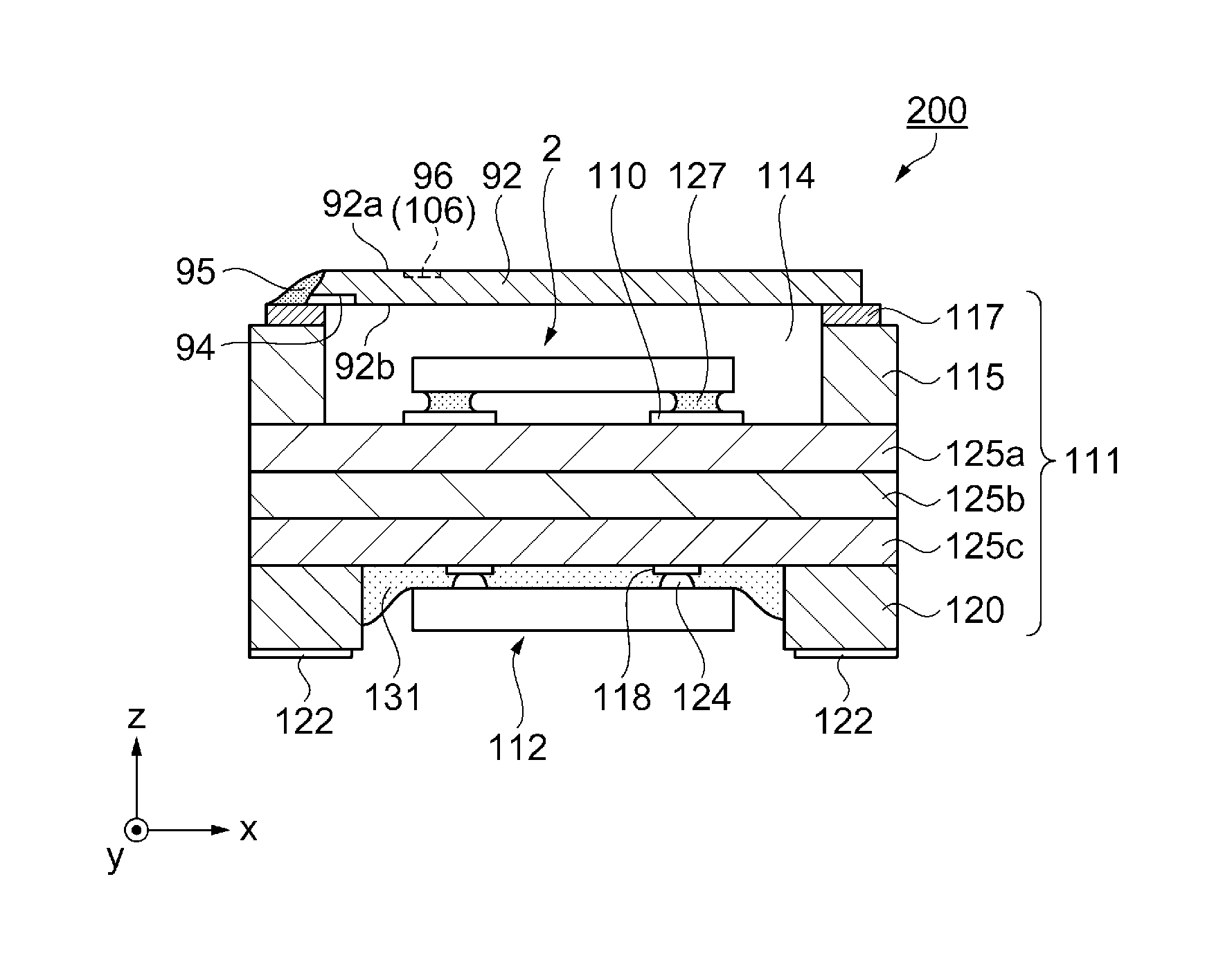
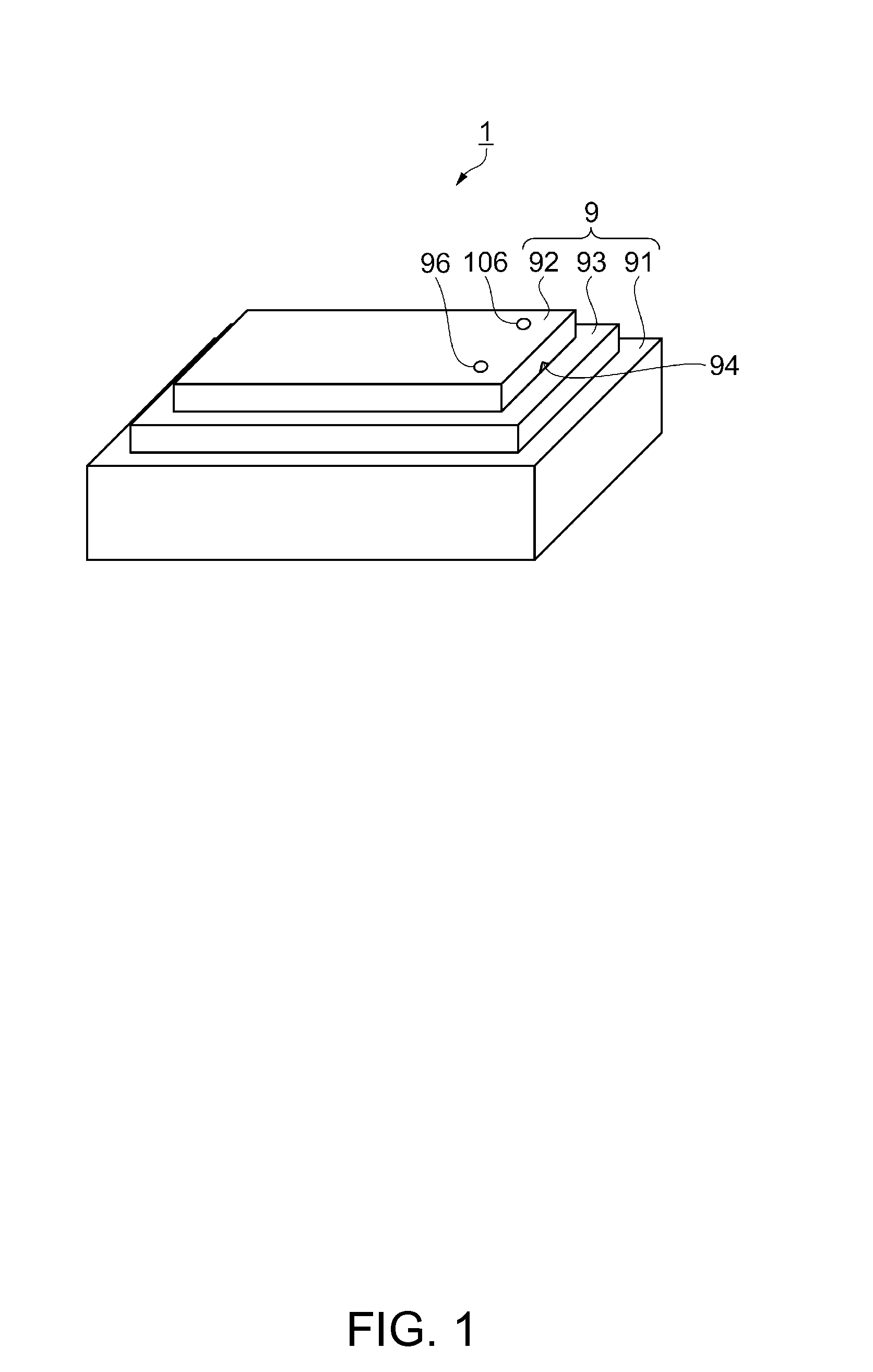
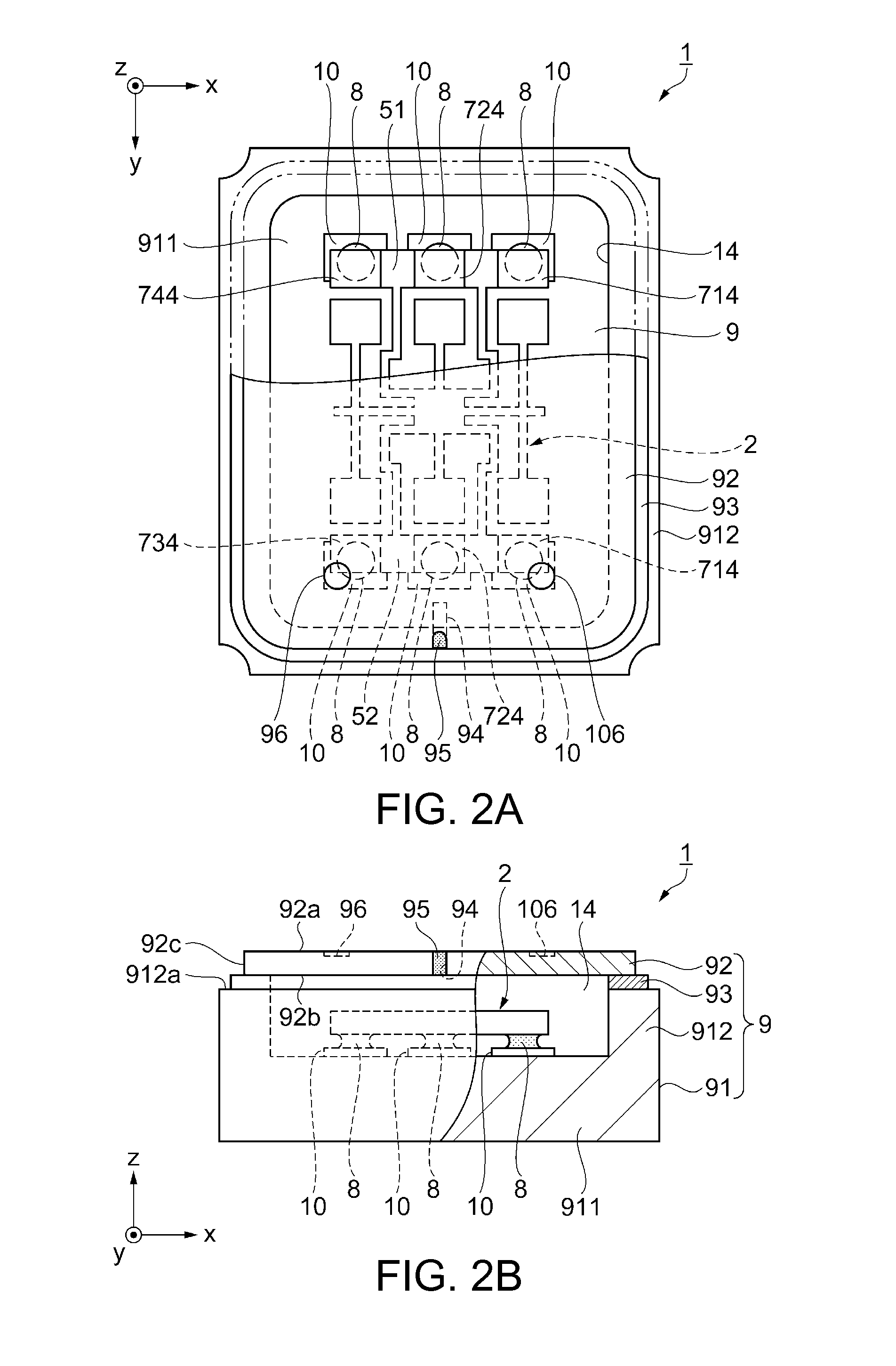
[0051]First, as a first embodiment of the invention, a package having a lid body, an oscillator as an electronic device using the package, and a method for manufacturing the oscillator will be described with reference to FIG. 1 to FIGS. 6A to 6D.
[0052]FIG. 1 is a schematic perspective view showing an oscillator as an electronic device using a lid body according to the invention. FIGS. 2A and 2B schematically show the oscillator according to the first embodiment. FIG. 2A is a plan view. FIG. 2B is a front cross-sectional view. FIG. 3 is a plan view showing a gyro element as an electronic component of the oscillator shown in FIGS. 2A and 2B. FIGS. 4A and 4B show an example of a lid body (lid) used for the oscillator. FIG. 4A is a plan view. FIG. 4B is a front cross-sectional view. FIGS. 5A to 5D are front cross-sectional views schematically showing the manufacturing process of the oscillator. FIGS. 6A and 6D show the joining state between a lid and a base. FIGS. 6A and 6C are plan vie...
modification 1
[0093]Referring to FIG. 7A, a modification 1 of the mark will be described. As the mark in the modification 1, a single first mark 96 is provided. The groove 94 is provided on the first surface (not shown) of the lid 92, and the first mark 96 is provided on the second surface 92a having a top-bottom relation with the first surface. The first mark 96 is provided on the second surface 92a of the lid 92 and at a position that does not overlap with the outer peripheral surface of the second surface 92a, that is, a position that overlaps with the groove 94, as viewed in a plan view.
[0094]As the first mark 96 is provided in this manner, the position of an end of the groove 94 can be directly recognized with the first mark 96. Therefore, the detection accuracy of the groove position is enhanced and the position accuracy of the position P3 where the laser beam 98 is directed can be improved. Thus, sealing failure of the groove 94 can be reduced.
modification 2
[0095]Referring to FIG. 7B, a modification 2 of the mark will be described. As the mark in the modification 2, a single mark 96a is provided. The groove 94 is provided on the first surface (not shown) of the lid 92, and the mark 96a is provided on the second surface 92a having a top-bottom relation with the first surface. The mark 96a is provided on the first imaginary straight line C which bisects the lid 92, connecting the center of the width of the groove 94 in the direction (x-axis direction in the illustration) intersecting with the extending direction (y-axis direction in the illustration) of the imaginary line (not shown) connecting the groove 94 and the center part of the second surface 92a, and the center G of the second surface 92a, as viewed in a plan view. The mark 96a is substantially rectangular (in this example, a rectangle) and extends on the first imaginary straight line C as the longitudinal direction thereof. The mark 96a has a first recognition area A1 and a seco...
PUM
 Abstract
Description
Claims
Application Information
 - R&D Engineer
- R&D Manager
- IP Professional
- Industry Leading Data Capabilities
- Powerful AI technology
- Patent DNA Extraction
Browse by: Latest US Patents, China's latest patents, Technical Efficacy Thesaurus, Application Domain, Technology Topic, Popular Technical Reports.
© 2024 PatSnap. All rights reserved.Legal|Privacy policy|Modern Slavery Act Transparency Statement|Sitemap|About US| Contact US: help@patsnap.com


