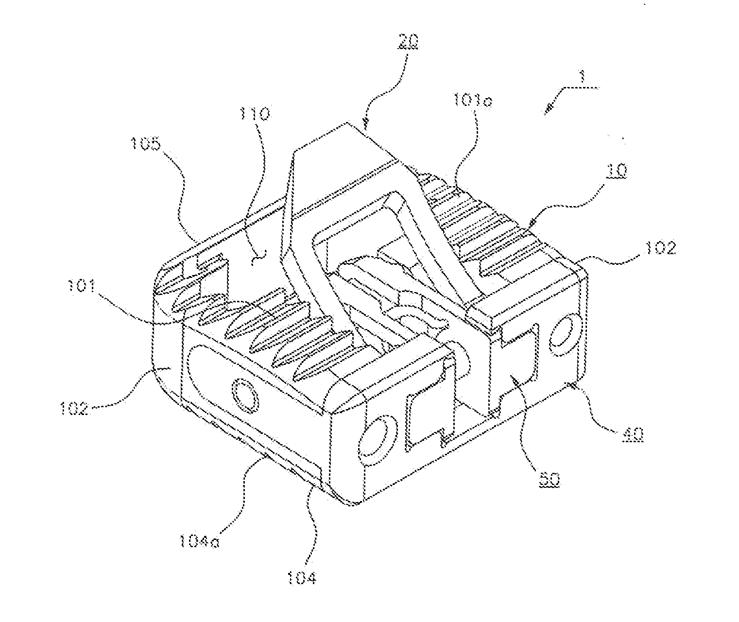
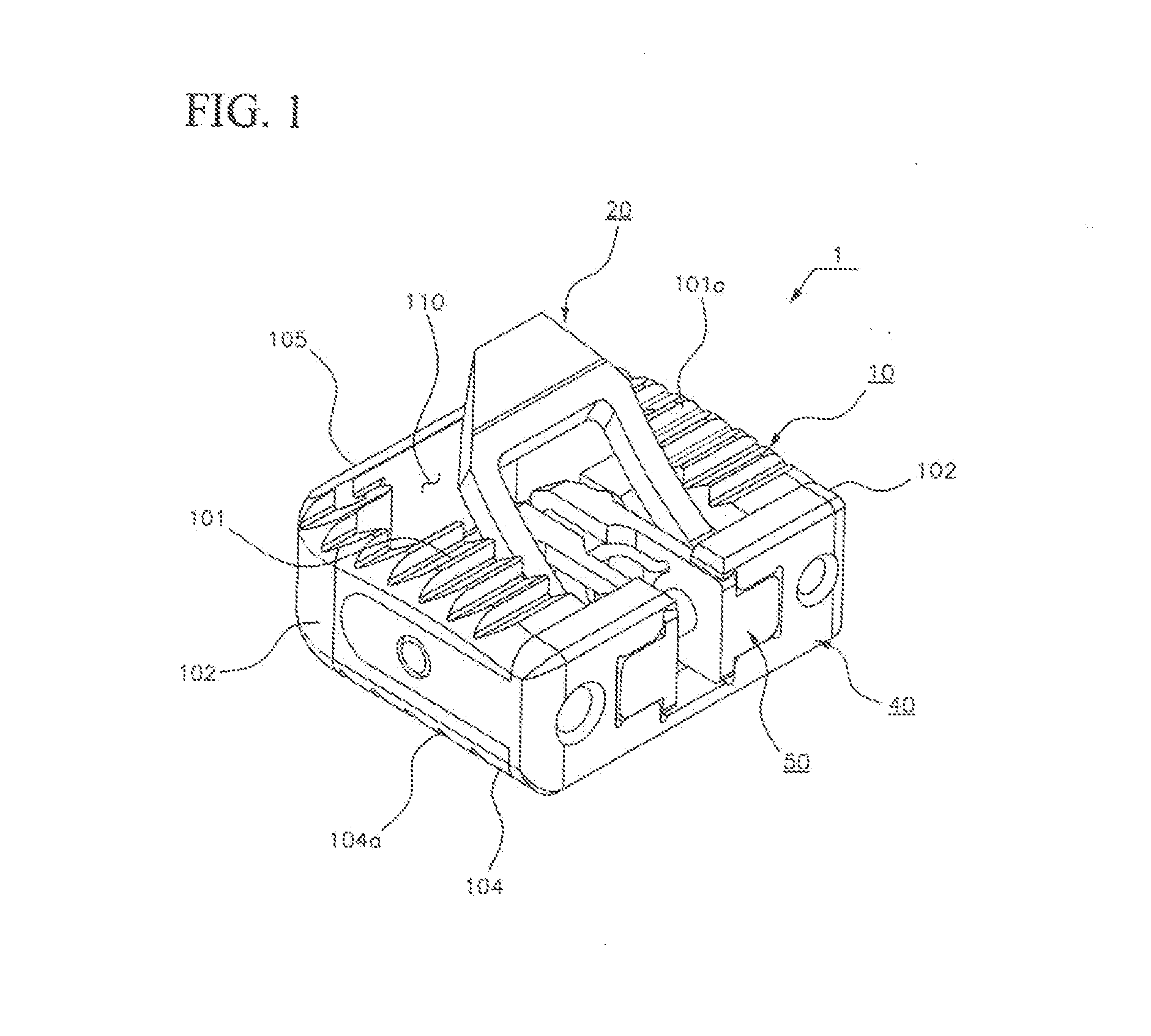
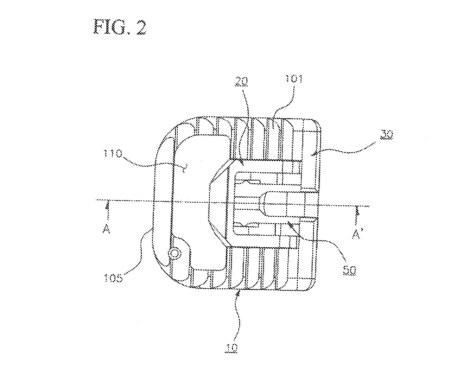
Cage having spike

Active Publication Date: 2015-05-07
LDR MEDICAL
View PDF3 Cites 62 Cited by
  • Summary
  • Abstract
  • Description
  • Claims
  • Application Information

AI Technical Summary

Benefits of technology

The present invention provides a cage with spikes that can prevent interference with blood or nerve tissues when placed in the spine. The cage is easy to fix and stable. This improves the stability and reduces the risk of complications during intervertebral disk surgery. Unlike other cages, the spikes help to omit a complicated and risky procedure of fixing a plate through a screw. Overall, this simplifies the procedure and improves patient outcomes.

Problems solved by technology

In this case, it is extremely difficult to fix the plate through the screw in such a small intervertebral space, while much attention is needed.

Method used


Image

  • Cage having spike
  • Cage having spike
  • Cage having spike

Examples


Embodiment Construction

[0033]Exemplary embodiments of the present invention will be described below in more detail with reference to the accompanying drawings. The present invention may, however, be embodied in different forms and should not be construed as limited to the embodiments set forth herein. Rather, these embodiments are provided so that this disclosure will be thorough and complete, and will fully convey the scope of the present invention to those skilled in the art. Throughout the disclosure, like reference numerals refer to like parts throughout the various figures and embodiments of the present invention.

[0034]The drawings are provided as examples for communicating the idea of the present invention to those skilled in the art. Thus, the present invention is not limited to the drawings, but may be embodied into other forms.

[0035]Furthermore, as long as terms used in this specification are not defined differently, the terms have meanings which are typically understood by those skilled in the a...


PUM


Abstract

The present invention relates to a cage which is inserted between vertebral bodies of a cervical vertebra or spine during an operation for treating a cervical disc disease, myelosis, or fracture of the cervical vertebra or spine, and more particularly, to a cage with spikes, including upper and lower spikes which are attached to a clip inserted into a main body of the cage, unfolded upward and downward from the main body, and locked to vertebral bodies of a cervical vertebra or spine positioned at the top and bottom of the cage such that the cage is fixed and locked between the vertebral bodies.

Description

CROSS-REFERENCE TO RELATED APPLICATIONS[0001]This application claims the benefit of Korean Patent Application No. 10-2013-108840, filed on Sep. 11, 2013 in the Korean Intellectual Property Office, which is incorporated herein by reference in its entirety.BACKGROUND OF THE INVENTION[0002]1. Field of the Invention[0003]The present invention relates to a cage which is inserted between vertebral bodies of a cervical vertebra or spine during an operation for treating a cervical disc disease, myelosis, or fracture of the cervical vertebra or spine, and more particularly, to a cage including upper and lower spikes which are attached to a clip inserted into a main body of the cage, unfolded to protrude from the top and bottom of the main body, and locked to vertebral bodies of a cervical vertebra or spine positioned at the top and bottom of the cage such that the cage is fixed between the vertebral bodies.[0004]2. Description of Related Art[0005]In general, an operation of inserting an arti...

Claims


Application Information

Patent Timeline
IPC IPC(8): A61F2/44A61F2/46
CPCA61F2/447A61F2002/30481A61F2002/30579A61F2/4611A61F2310/00131A61F2310/00017A61F2310/00023A61F2310/00029A61F2310/00089A61F2310/00095A61F2002/30822A61F2002/30904A61F2002/30892A61F2002/30492A61F2002/305A61F2002/30484A61F2002/30373A61F2310/00239A61F2002/30433A61F2002/30624A61F2002/30593A61B17/70A61F2/442
Inventor KIM, SEO-KONKIM, II
Owner LDR MEDICAL
Why Eureka
Try Eureka