Vehicle suspension arm

a technology of suspension arm and suspension plate, which is applied in the direction of shaft and bearing, mechanical equipment, transportation and packaging, etc., can solve the problems of material loss and the formation of the entire arm body, and achieve the effects of reducing the weight reducing the size of the entire arm, and simplifying the shape of the components

Inactive Publication Date: 2015-04-30
YOROZU
View PDF36 Cites 11 Cited by
  • Summary
  • Abstract
  • Description
  • Claims
  • Application Information

AI Technical Summary

Benefits of technology

[0013]According to the invention of claim 1, since the arm body includes a pair of side plates opposed to each other and a bottom plate connecting the side plates and the side plates are arranged to extend within a lower surface area of spring receiving seat of the spring receiving seat member, the spring receiving seat member is supported by the side plates, the side plates are not affected by the size of the spring receiving seat member, the side plates are not increased in size with the size of the spring receiving seat member as in the related art, and the suspension arm itself can be reasonably reduced in size. Furthermore, since the spring receiving seat member is supported by the side plates and the suspension coil spring is placed on the spring receiving seat member, the spring receiving seat part does not have such a double structure as in the related art, the shapes of the components can be made simpler, the weight of the entire arm can be reduced, little waste material is caused in press forming, the manufacture cost can be reduced, and there is thus a significant advantage in cost.
[0014]According to the invention of claim 2, since the spring receiving seat member is formed of a plate material having a flat structure having a support part supporting the end part of the suspension coil spring, various sizes of suspension coil springs can be supported to some extent, the spring receiving seat member itself can have a simple shape, without being increased in size, and the suspension arm can also be made smaller.
[0015]According to the invention of claim 3, since the spring receiving seat member is arranged in notched recess parts formed in the upper faces of the side plates of the arm body, the spring receiving seat member can be firmly and stably attached to the arm body.
[0016]According to the invention of claim 4, since the spring receiving seat member is supported by the side plates, the damper insertion hole and the weight reducing holes formed in the side plates or the bottom plate between the side plates can be enlarged or provided in large quantity. Furthermore, since reinforcement beads are formed near the holes, the weight can be reduced while maintaining the stiffness or the strength of the suspension arm.
[0017]According to the invention of claim 5, since a reinforcement plate is provided between ends of the side plates of the arm body and connected with the side plates by welding, the stiffness or the strength of the side plates can be further improved.

Problems solved by technology

Thus, a lump formation of the entire arm body by pressing is difficult and is likely to cause material loss.

Method used


Image

  • Vehicle suspension arm
  • Vehicle suspension arm
  • Vehicle suspension arm

Examples


Embodiment Construction

[0025]An embodiment of the present invention will be described below with reference to the drawings.

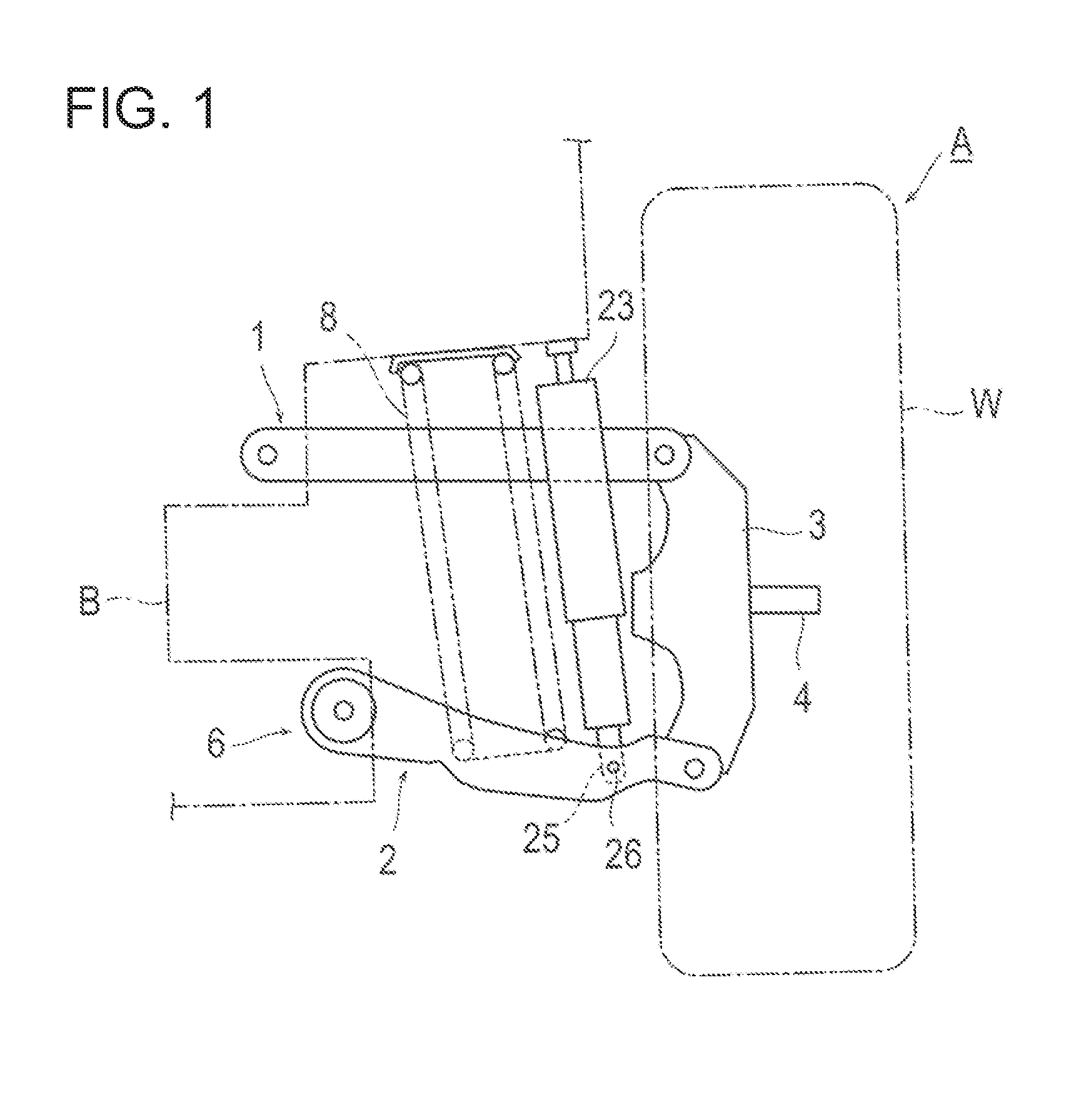
[0026]Suspension according to the embodiment includes an upper arm 1 and a lower arm 2 as illustrated in FIG. 1. One end of each of the arms 1 and 2 is connected to a vehicle body B side, and the other end thereof is connected to a knuckle 3 of an axle A side. In the drawing, a reference “W” represents a wheel and a reference “4” represents an axle shaft.

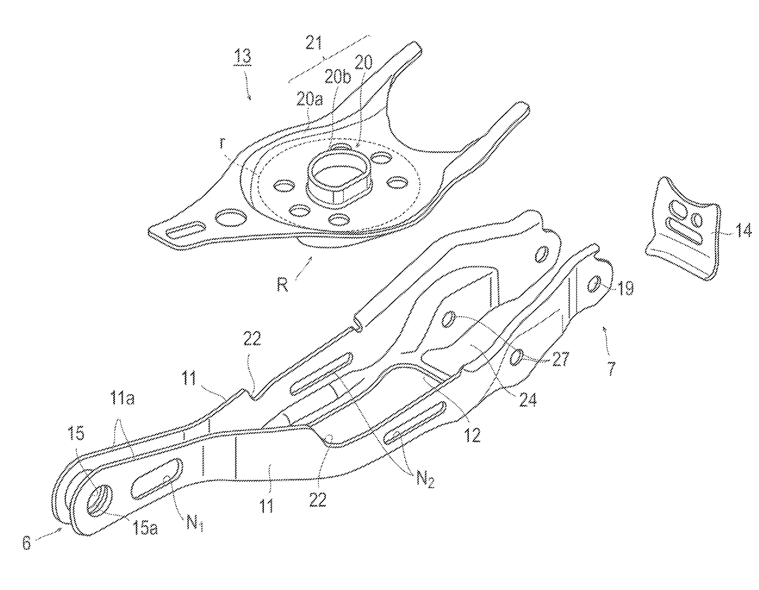
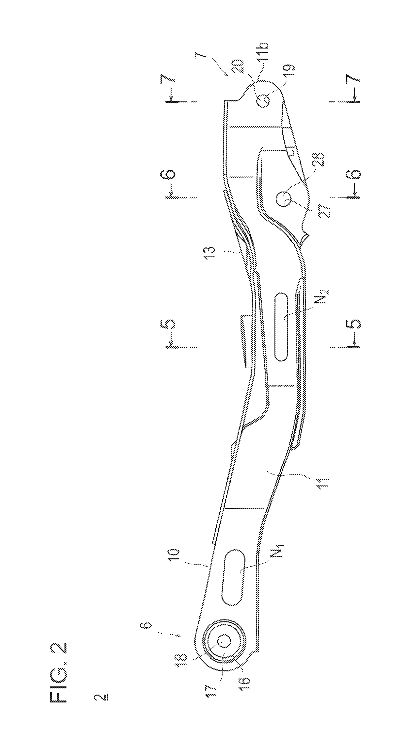
[0027]As illustrated in FIGS. 1 and 2, the lower arm 2 has a long arm body 10, a spring receiving seat member 13 that is provided at an upper part of the arm body 10 and supports a suspension coil spring 8, and connecting portions 6 and 7 which are provided at respective ends of the arm body 10 and connected to the axle A side or the vehicle body B side.

[0028]As illustrated in FIGS. 2 and 3, the arm body 10 has a U-shaped cross-section and an entire structure generally open at the top, and the arm body 10 includes a pair of side plate...


PUM


Abstract

[Problem] To provide a vehicle suspension arm including components having simple shapes, being reasonably reduced in size and weight, and capable of being manufactured at low cost.
[Solution] In formation of a lower arm 2 for vehicle suspension, an arm body 10 includes a pair of side plates 11 opposed to each other, a bottom plate 12 formed integrally to connect the side plates 11, and a spring receiving seat member 13 attached to the side plates 11, wherein the side plates 11 are arranged to extend within a lower surface area R of the spring receiving seat member 13.

Description

TECHNICAL FIELD[0001]The present invention relates to a vehicle suspension arm whose components having simple shapes and whose entire structure reasonably reduced in size.BACKGROUND ART[0002]There are various forms of vehicle suspension. For example, there is a vehicle suspension in which one end of an upper arm is connected to an upper part of a knuckle which is disposed at an axle side, one end of a lower arm is connected to a lower part of the knuckle, the other ends of these arms are connected to the vehicle body side, and a suspension coil spring and a damper are provided between the lower arm and the vehicle body.[0003]The lower arm has a long arm body, a connecting part provided at an end of the arm body, and a spring receiving seat member provided at substantially the center of the arm body. The suspension coil spring is provided on the spring receiving seat member and a lower end of the damper is attached near the knuckle of the arm body.[0004]In the lower arm, since the sp...

Claims


Application Information

Patent Timeline
Patent Type & Authority Applications(United States)
IPC IPC(8): B60G7/00B60G15/06
CPCB60G15/067B60G7/001B60G11/16B60G2200/144B60G2204/1244B60G2202/12B60G2204/129B60G2204/143B60G2204/148B60G2206/017B60G2206/11B60G2206/162B60G2206/722B60G2206/8102B60G2206/8103B60G2206/8109B60G2206/8201B60G2206/91F16C7/08F16C2326/05
Inventor NAKASATO, HIDETOSHIBABA, YOICHI
Owner YOROZU
Why Eureka
Try Eureka