
Storage rack

Inactive Publication Date: 2015-04-30
LEE WAN YOUNG
View PDF39 Cites 3 Cited by
  • Summary
  • Abstract
  • Description
  • Claims
  • Application Information

AI Technical Summary

Benefits of technology

The present invention is a storage rack designed to increase space availability and efficiency by having a low rack height and keeping goods at a minimum distance from horizontal support beams. This design also provides structural stability. By fastening the end of the goods supporting post to the horizontal support beam to be overlapped therewith, space availability is increased and structural stability is provided. Additionally, by disposing one horizontal support beam between the lattice posts, assembly of the storage rack during installation is simplified, reducing installation cost and period. Furthermore, the layered goods can be maintained at a minimum regular distance in a vertical direction, simplifying the motion line of distribution of the goods and preventing unnecessary confusion of control, making management of the goods easier.

Problems solved by technology

Thus, there are many problems in that the product may be deformed or damaged due to contact between the product and equipment when the product is handled and the product may fall down and be dropped by being slanted due to rotational inertia when the products are moved in a motion line of distribution of the products.
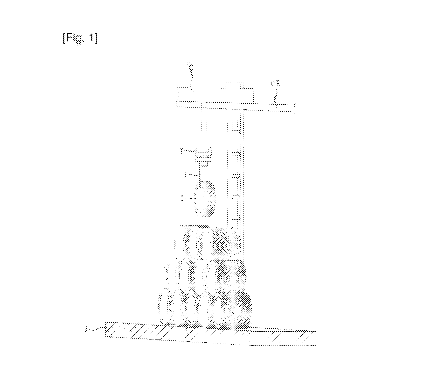
Accordingly, in such a storing method, since the products 2 come in direct contact with the bottom 3 and are upwardly stored to be layered in four to five stages, there are a decrease in efficiency of storage space and limitations in storage capacity.
Further, it is difficult to selectively stock or rotate the products.
In addition, when the products are handled or delivered, manpower is largely required due to frequent operations of delivery equipment such as the forklift or the C-shaped hook unit 1 attached to the trolley T suspended from the ceiling crane C. There is a problem in that such a goods handling method is economically inefficient.
Moreover, the products may be scratched or damaged due to contact between the bottom 3 and the products 2, contact between the layered products 2, and frequent movements (deliver and shipment) of the goods.
Especially when the products are stored in the outdoors, since the products are exposed to moisture, the products may be severely corroded.
For this reason, since installation positions of goods hanging beams are not constant in a vertical direction, it may be highly likely to delay time in controlling the stock and rotation of the goods, and the height of the entire rack may increase.

Method used


Image

  • Storage rack
  • Storage rack
  • Storage rack

Examples


Embodiment Construction

[0054]Hereinafter, the present invention will be described in more detail with reference to the accompanying drawings.

[0055]The terms “module” and “part” that represent components used in the following description are merely used to easily draft the present specification, and the terms “module” and “part” may be used together with.

[0056]Embodiments of the present invention will be described in detail with reference to the accompanying drawings and the contents described in the accompanying drawings, but the present invention is not limited to the embodiments.

[0057]As the terms used in the present specification, general terms that are widely used in recent years in consideration of functions in the present invention are selected, but may be changed depending on intention of those skilled in the art, practices, or new technology. In specific cases, the applicant may arbitrarily select the terms. In this case, the meaning of the terms will be described in the detailed description of th...


PUM


Abstract

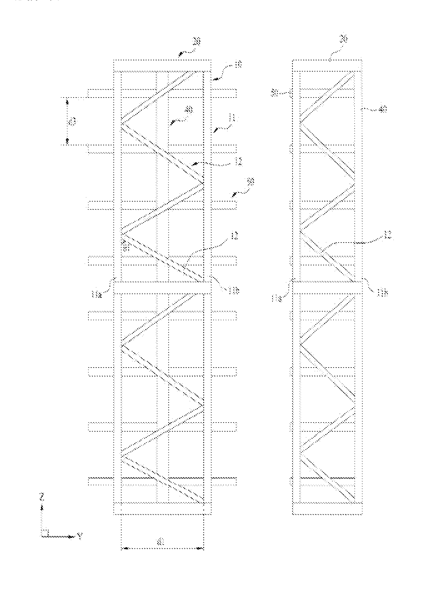
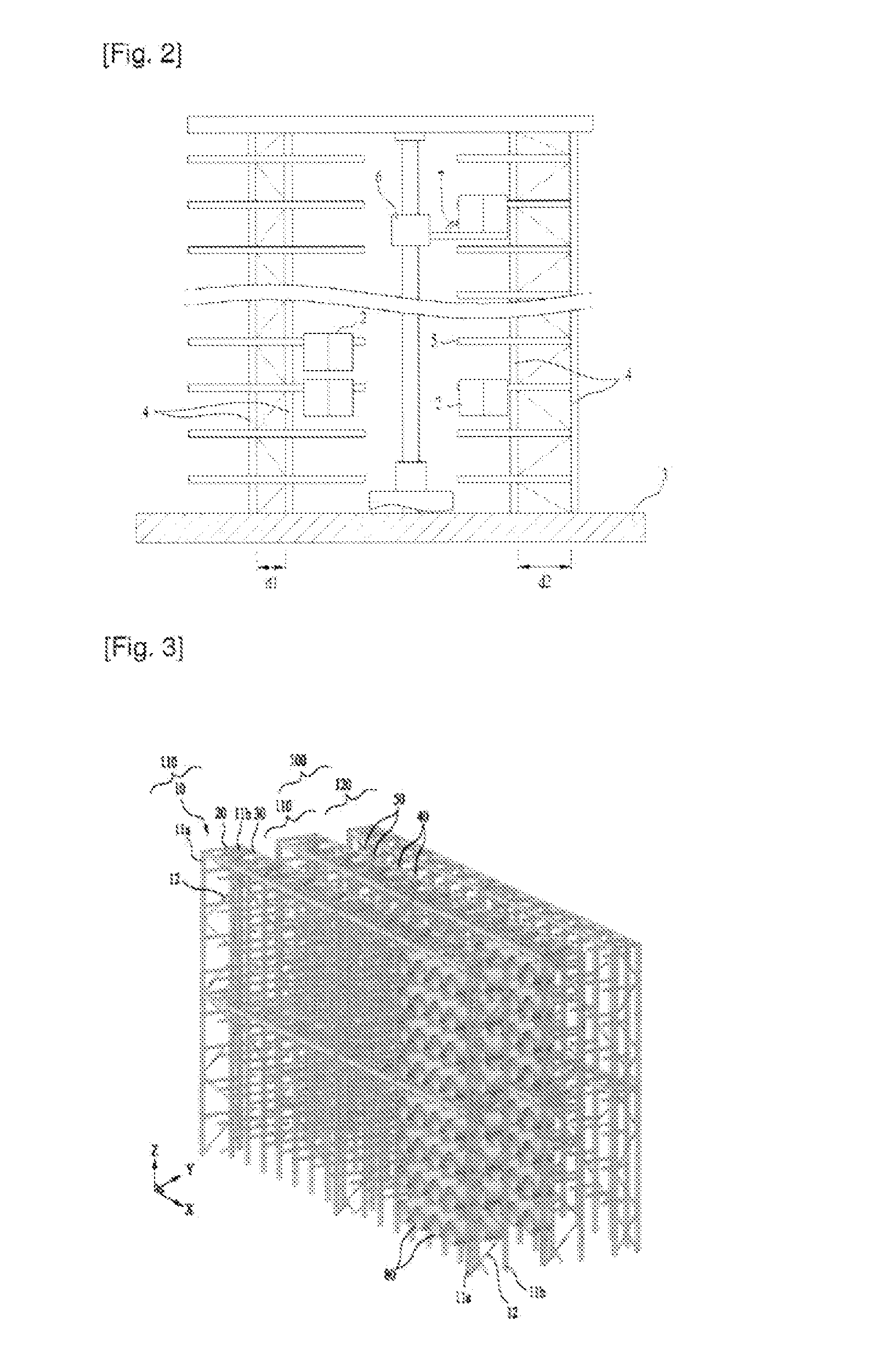
There is a storage rack includes a plurality of lattice posts that include first and second post elements arranged in a Y-axis direction at a first distance, and vertical lattice members connecting the first and second post elements; a post connecting beam that connects the first and second post elements of the lattice post; a horizontal support beam whose ends are fastened to centers of the post connecting beams to connect the lattice posts arranged in an X-axis direction at a second distance; a plurality of goods supporting posts whose ends are fastened along a central line of the horizontal support beam to be arranged between the lattice posts arranged at the second distance at a predetermined distance along the goods layering spaces; and a plurality of goods supporting beams whose ends are fastened to the goods supporting post to be arranged in a Z-axis direction at a third distance.

Description

CROSS-REFERENCE TO RELATED APPLICATIONS[0001]This application claims the benefit of priority of Korean Patent Application No. 10-2013-0130599 filed on Oct. 30, 2013, the disclosure of which is incorporated herein by reference.BACKGROUND OF THE INVENTION[0002]1. Field of the Invention[0003]The present invention relates to a storage rack that stores goods.[0004]2. Description of the Related Art[0005]In general, as cylindrical products having hollow portions, there are various products wound in a cylindrical shape such as steel plate coils, wire rods or bar in coil, tires, fibers, and newspapers.[0006]Among the cylindrical products having hollow portions, the product required to be minutely handled may be the wire rod.[0007]Since the wire rod is formed by winding a plurality of coils in a circular shape, the wire rod is lengthened due to its elasticity. Thus, there are many problems in that the product may be deformed or damaged due to contact between the product and equipment when the...

Claims


Application Information

Patent Timeline
IPC IPC(8): B65H49/32B65H49/16
CPCB65H49/16B65H49/324B65H49/38B65G1/02
Inventor LEE, WAN YOUNG
Owner LEE WAN YOUNG
Learn More