
In-band OSNR measurement on polarization-multiplexed signals

a polarization-multiplexed optical and in-band osnr technology, applied in the direction of electrical equipment, transmission monitoring, electromagnetic transmission, etc., can solve the problems of inability to reliably provide osnr measurement, disruptive and normally unsuitable use, and completely unsuitable “monitoring” applications, so as to reduce the cost and thermal dissipation of electronic components, reduce detection bandwidth, and induce significant errors in osnr determination

Active Publication Date: 2015-04-23
EXFO
View PDF4 Cites 27 Cited by
  • Summary
  • Abstract
  • Description
  • Claims
  • Application Information

AI Technical Summary

Benefits of technology

The present invention provides a method and system for measuring in-band noise parameters on a polarization-multiplexed optical signal-under-test (SUT) that addresses concerns associated with previous methods. The method involves analyzing the SUT using a polarization-optics arrangement to provide at least one polarization-analyzed component of the SUT, and obtaining a corresponding electrical signal with an electronic bandwidth at least ten times smaller than the symbol rate of the SUT. The statistical parameters determined from the acquired electrical signals are used to calculate the in-band noise parameter, which is representative of the optical noise contribution. The method and system can provide reliable and accurate measurement of the in-band noise parameter even in the presence of high levels of chromatic dispersion or other factors that may induce errors.

Problems solved by technology

However, such methods are based on the assumption that the signal is generally highly polarized, an assumption that is not valid in the case of polarization-multiplexed signals.
For the case of most polarization-multiplexed signals, the “signal”, as detected on a photodiode having low bandwidth electronics for instance, appears unpolarized, and hence, these above-mentioned in-band OSNR measurement methods cannot be used to reliably provide the OSNR measurement.
A first limitation of this method is that it is highly disruptive and normally unsuitable for use in a “live” (i.e. carrying commercial payload) network, and is completely unsuitable for “monitoring” applications.
The fact that this method requires that a reference signal be measured may be considered as a drawback for some applications.
This approach would likely not be commercially viable for use as a widely-deployed DWDM signal monitor, due to the inherently high cost of employing electronics having roughly the same bandwidth as the signal symbol rate.
However, it was realized that not only is this not necessary to evaluate the in-band optical noise but that it is also detrimental in certain aspects.
More specifically, the approach of Saida et al. does not address the issue as to how to measure OSNR in the presence of Chromatic Dispersion (CD).
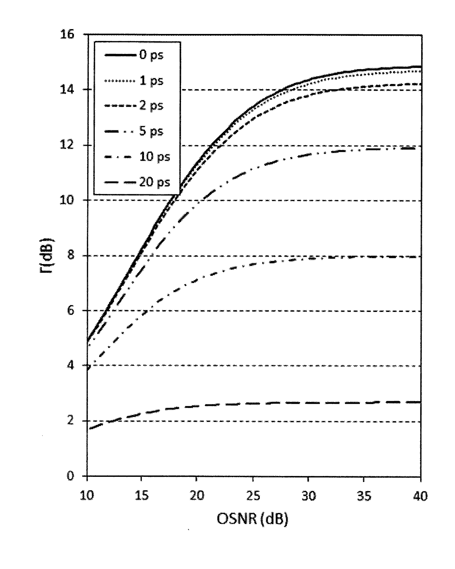
As shown herein, CD may induce significant errors in the OSNR determination, especially for high OSNR values or large CD values.

Method used


Image

  • In-band OSNR measurement on polarization-multiplexed signals
  • In-band OSNR measurement on polarization-multiplexed signals
  • In-band OSNR measurement on polarization-multiplexed signals

Examples


Embodiment Construction

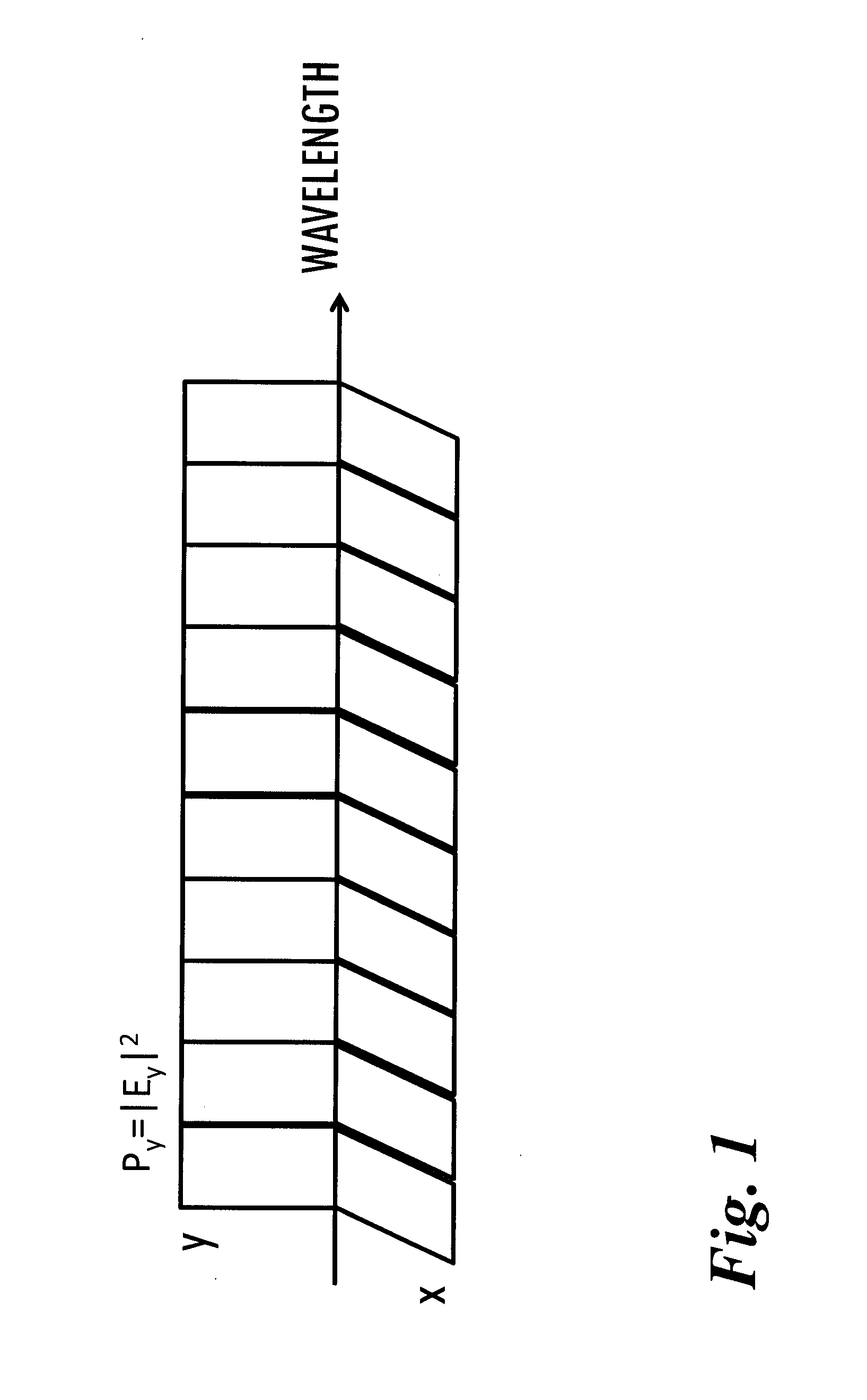
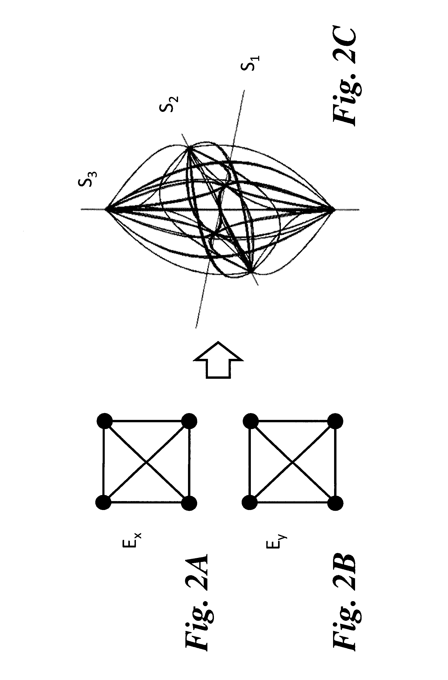
[0046]Referring to FIG. 1, a PolMux signal normally comprises two polarized data-carrying contributions that are mutually-orthogonal, i.e. signals whose respective Stokes parameters differ only by a polarity (i.e. + or −). Conceptually and without loss of generality, these two signals may be considered to be respectively linearly aligned with arbitrary x and y axes, with corresponding electrical fields Ex and Ey. The basis of the Stokes coordinates may be rotated so that, for instance, the optical-carrier electrical field of the first data-carrying signal Ex is aligned with S1, and that of the optical-carrier electrical field of the second data-carrying signal Ey is aligned with −S1, as illustrated in FIG. 1. Apart from the data-carrying signal contributions, the Signal-Under-Test (SUT) generally comprises an optical noise contribution which includes all other sources of optical power within the optical channel. The optical noise contribution typically arises mostly from the Amplifi...


PUM


Abstract

There is provided a system and a method for determining an in-band noise parameter representative of the optical noise contribution (such as OSNR) on a polarization-multiplexed optical Signal-Under-Test (SUT) comprising two polarized phase-modulated data-carrying contributions and an optical noise contribution. For each of a multiplicity of distinct polarization-analyzer conditions, the SUT is analyzed to provide at least one polarization-analyzed component of the SUT and the polarization-analyzed component is detected with an electronic bandwidth at least ten times smaller than the symbol rate of the SUT to obtain a corresponding acquired electrical signal; for each acquired electrical signal, a value of a statistical parameter is determined from the ac component of the acquired electrical signal, thereby providing a set of statistical-parameter values corresponding to the multiplicity of distinct polarization-analyzer conditions; and, from the set of statistical-parameter values, the in-band noise parameter is mathematically determined.

Description

CROSS-REFERENCE TO RELATED APPLICATIONS[0001]This application claims priority under 35USC§119(e) of U.S. provisional patent application 61 / 893,948 filed Oct. 22, 2013, the specification of which is hereby incorporated by reference.TECHNICAL FIELD[0002]The invention relates to the determination of the in-band noise in optical telecommunication applications. More specifically, the invention relates to the determination of the in-band noise on polarization-multiplexed optical signals.BACKGROUND OF THE ART[0003]In order to maximize the information content transmitted over a given spectral bandwidth (often measured in bits per Hz of spectral bandwidth), polarization multiplexing (referred to as “PolMux”) is being increasingly used with new transmission formats. The underlying idea is that the spectral efficiency (conveniently measured in units of bits / Hz) can be effectively doubled by employing two orthogonally polarized data-carrying signals, typically having the same symbol rate, shari...

Claims


Application Information

Patent Timeline
IPC IPC(8): H04B10/079H04J14/06
CPCH04J14/06H04B10/07953
Inventor SUNNERUD, HENRIKSKOLD, MATSWESTLUND, MATHIAS
Owner EXFO
Learn More