
Deployable and Multi-Sectional Hearing Implant Electrode

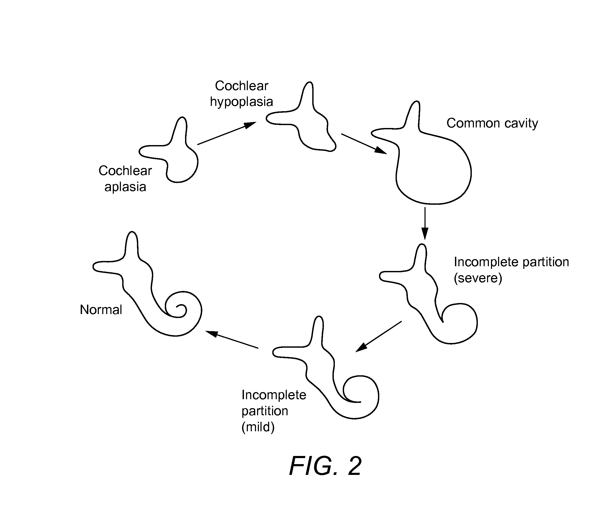
a multi-sectional, implantable technology, applied in the field of medical implants, can solve the problems of undetectable trauma, difficult placement of electrodes inside the common cavity, and impaired hearing

Inactive Publication Date: 2015-04-16
MED EL ELEKTROMEDIZINISCHE GERAETE GMBH
View PDF7 Cites 16 Cited by
  • Summary
  • Abstract
  • Description
  • Claims
  • Application Information

AI Technical Summary

Benefits of technology

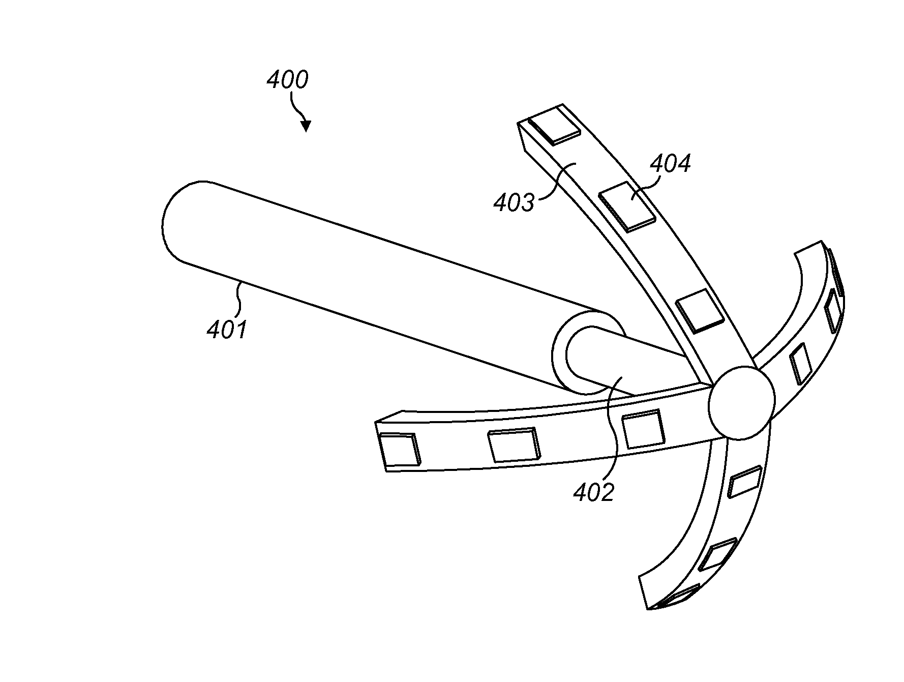
The present invention is about an electrode for a cochlear implant that can be inserted into a malformed cochlea with a single internal cavity. The electrode has a single tube containing signal wires for conducting electrical stimulation signals. The electrode array is designed to be inserted through a single cochleostomy opening and opened within the cochlea to deliver the electrical stimulation signals to adjacent neural tissue for auditory perception by the patient. The electrode array has outer array branches that move away from the center axis to lie against the outer cavity wall of the cochlea. The electrode array can be closed into a single tube and opened within the cochlea. The invention also includes a cochlear implant system with the electrode array.

Problems solved by technology

Hearing is impaired when there are problems in the ability to transduce external sounds into meaningful action potentials along the neural substrate of the cochlea.
Placing an electrode inside this common cavity is not straightforward and needs utmost care to ensure that the stimulation contacts are either touching or very close to the outer wall of the cavity.
The current technique involves making two cochleostomy openings in the outer surface of the cochlea for the electrode placement, which is undesirably traumatic.
Both techniques are highly traumatic in requiring two cochleostomies and both require considerable surgical skill to be effective.

Method used


Image

  • Deployable and Multi-Sectional Hearing Implant Electrode
  • Deployable and Multi-Sectional Hearing Implant Electrode
  • Deployable and Multi-Sectional Hearing Implant Electrode

Examples


Embodiment Construction

[0031]Various embodiments of the present invention are directed to an implantable electrode for a common cavity cochlea having a foldable electrode array configured for insertion into the cochlea through a single cochleostomy. After entering the common cavity, the electrode array is unfolded to place array branches with the stimulating contacts adjacent to the outer cavity wall. Because the electrode is configured for insertion through a single cochleostomy opening rather than requiring two cochleostomies as in existing conventional arrangements, the amount of trauma to the cochlea is reduced and an easier surgical insertion process can be used. Further, the probability to make contact with neural elements is increased, which location and distribution inside malformed cochleae cannot be predicted by preoperative examinations.

[0032]FIG. 4 A-B show a common cavity electrode 400 having an umbrella shape according to an embodiment of the present invention. The common cavity electrode 40...


PUM


Abstract

An implantable electrode is described for a cochlear implant patient with a malformed common cavity cochlea having a single internal cavity defined by an outer cavity wall or patients having an incomplete partition or conventional spiral-shaped cochlea. An intra-cochlear electrode array is configured to be inserted into the cochlea through a single cochleostomy opening. Outer array branches are closable about a center axis and the electrode array is configured to be closed into a single tube including the array branches for insertion through the single cochleostomy opening into the internal chamber of the cochlea. The electrode array opens within the internal cavity after insertion into the cochlea so that the array branches move away from the center axis to lie with their outer surfaces against the outer cavity wall to deliver the electrical stimulation signals through the stimulation contacts to adjacent neural tissue for auditory perception by the patient.

Description

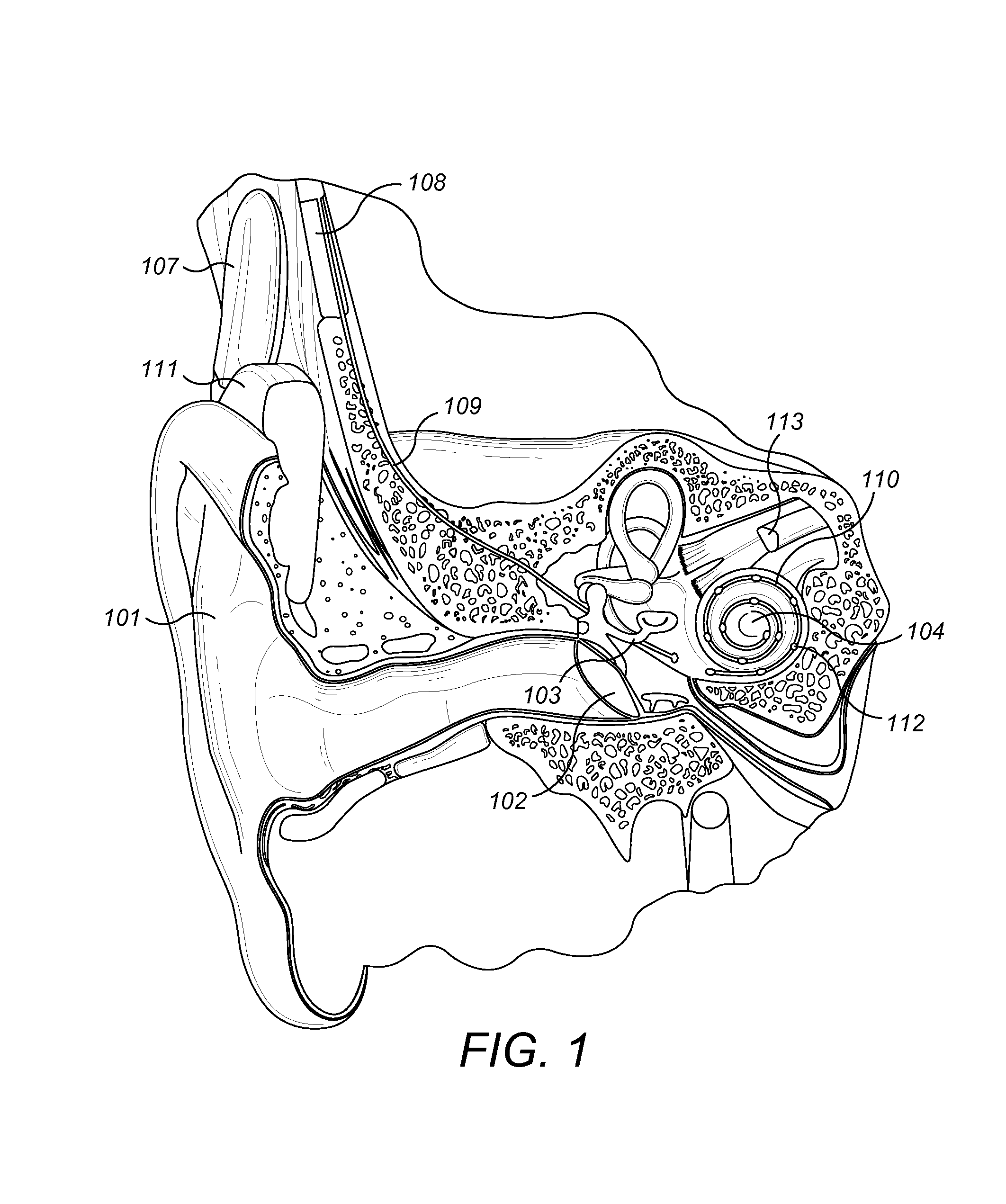
[0001]This application claims priority from U.S. Provisional Patent Application 61 / 890,923, filed Oct. 15, 2013, which is incorporated herein by reference in its entirety.FIELD OF THE INVENTION[0002]The present invention relates to medical implants, and more specifically to an implantable electrode for use in cochlear implant systems in patients having a malformed cochlea.BACKGROUND ART[0003]A normal ear transmits sounds as shown in FIG. 1 through the outer ear 101 to the tympanic membrane (eardrum) 102, which moves the bones of the middle ear 103 (malleus, incus, and stapes), which in turn vibrate the oval window and round window openings of the cochlea 104. The cochlea 104 is a long narrow duct wound spirally about its axis for approximately two and a half turns. The cochlea 104 includes an upper channel known as the scala vestibuli and a lower channel known as the scala tympani, which are connected by the cochlear duct. The scala tympani forms an upright spiraling cone with a cen...

Claims


Application Information

Patent Timeline
IPC IPC(8): A61N1/05
CPCA61N1/0541
Inventor LENARZ, THOMASDHANASINGH, ANANDHANJOLLY, CLAUDEHOCHMAIR, INGEBORGRIDL, ANITA
Owner MED EL ELEKTROMEDIZINISCHE GERAETE GMBH
Learn More