
Overvoltage protection device

a protection device and overvoltage technology, applied in the direction of overvoltage protection resistors, emergency protection circuit arrangements, emergency protection arrangements for limiting excess voltage/current, etc., can solve the problems of overload of connecting regions, melting of connecting regions, and destruction of connecting regions, etc., to achieve simple and economical construction and mounting, durable and long-lasting

Inactive Publication Date: 2015-04-16
PHOENIX CONTACT GMBH & CO KG
View PDF16 Cites 14 Cited by
  • Summary
  • Abstract
  • Description
  • Claims
  • Application Information

AI Technical Summary

Benefits of technology

The invention is an overvoltage protection device that is durable and long-lasting. It is designed to be simple and economical to build and mount. The device has a cylindrical fusible element with low inductance, which reduces the need for a large protection level. It also has a high-power varistor and a gas-filled surge arrester to handle high rated voltages. The device has a status display that can easily be recognized from the outside. The technical effects of the invention include improved durability, reduced inductance, and efficient protection against overvoltage.

Problems solved by technology

Conversely, line-frequency short circuit currents which in a fault case flow via the overvoltage protection device and thus also via the connecting region lead to an overload of the connecting region so that the connecting region melts and is thus destroyed.

Method used


Image

  • Overvoltage protection device
  • Overvoltage protection device
  • Overvoltage protection device

Examples


Embodiment Construction

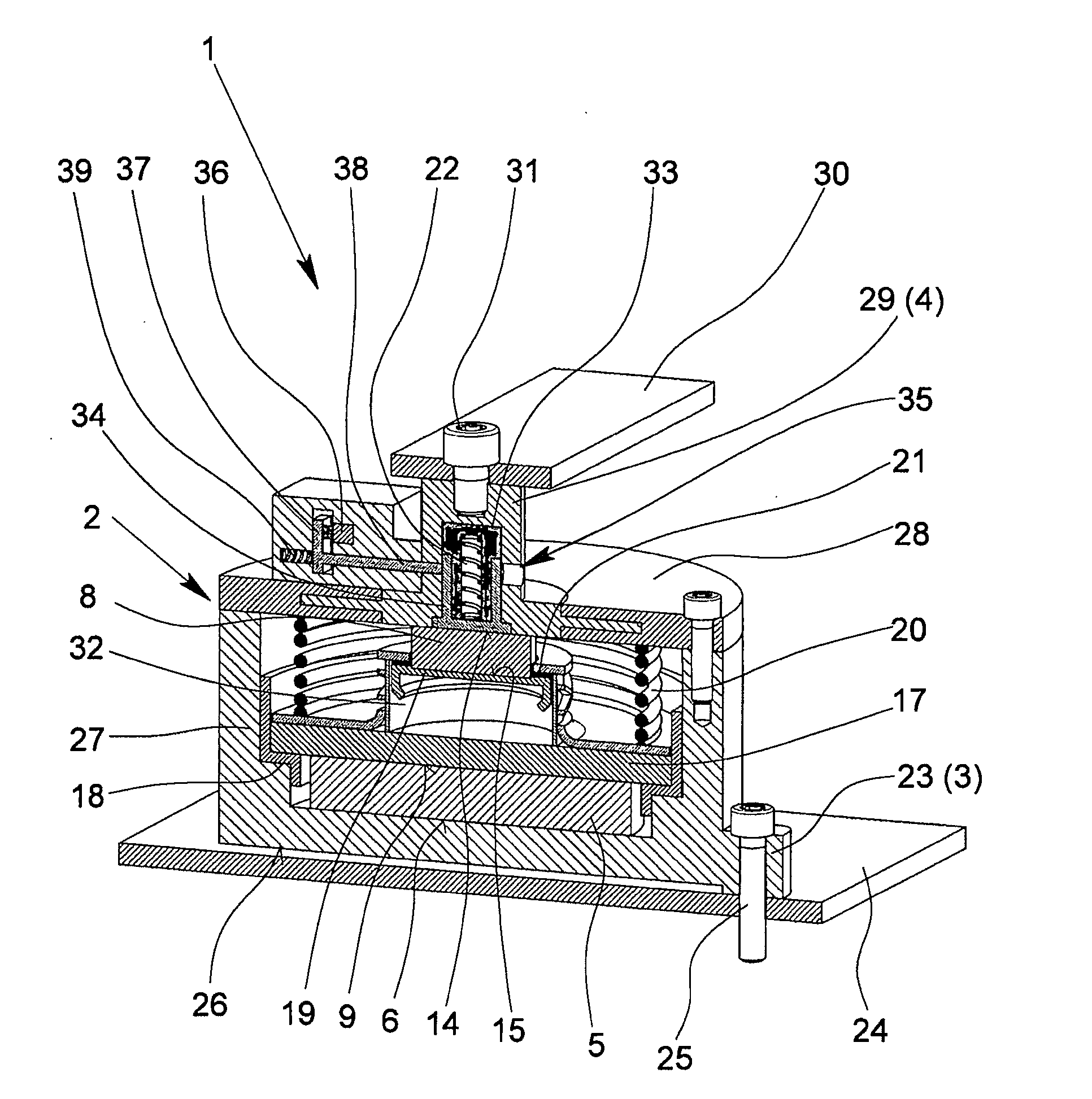
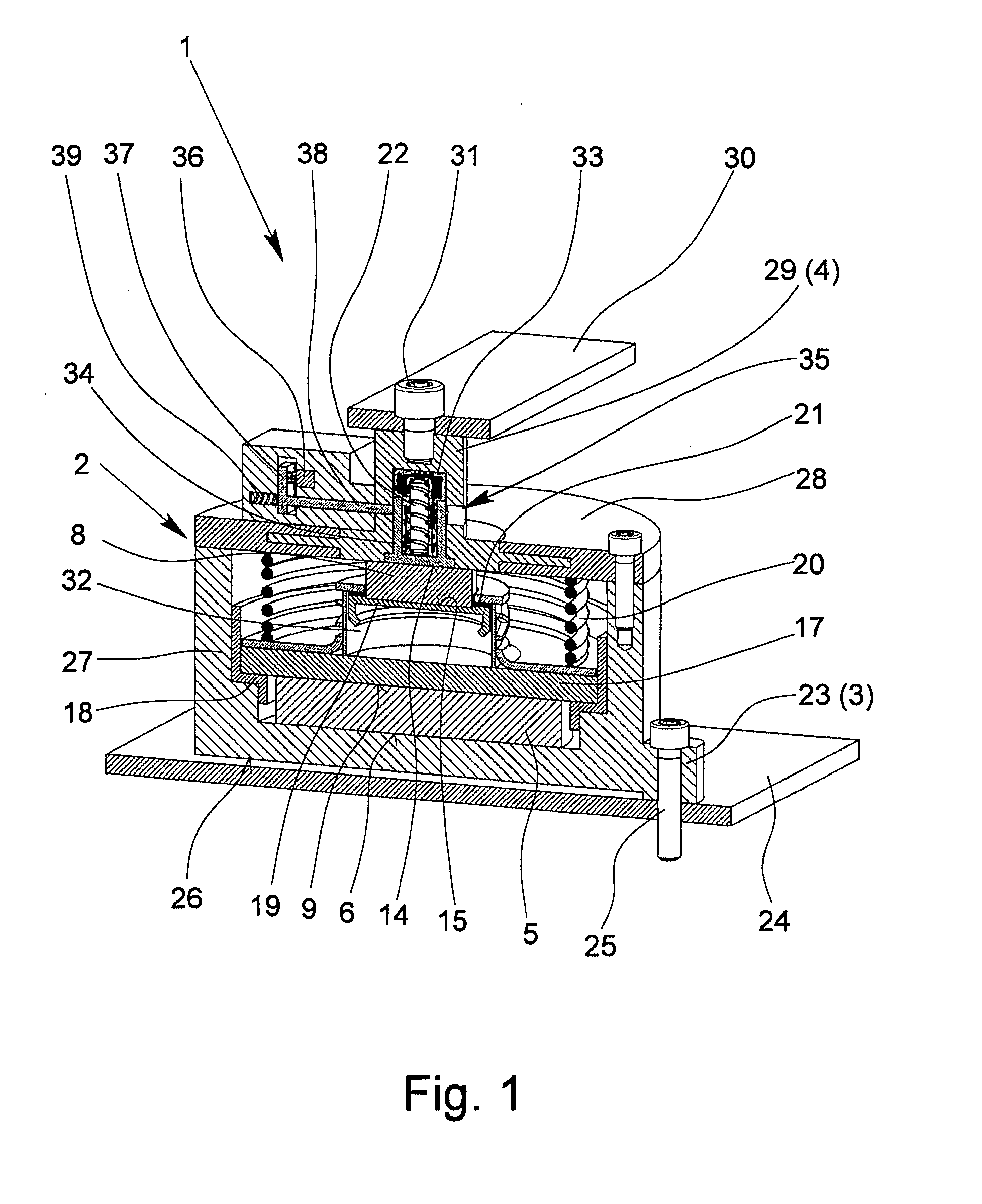
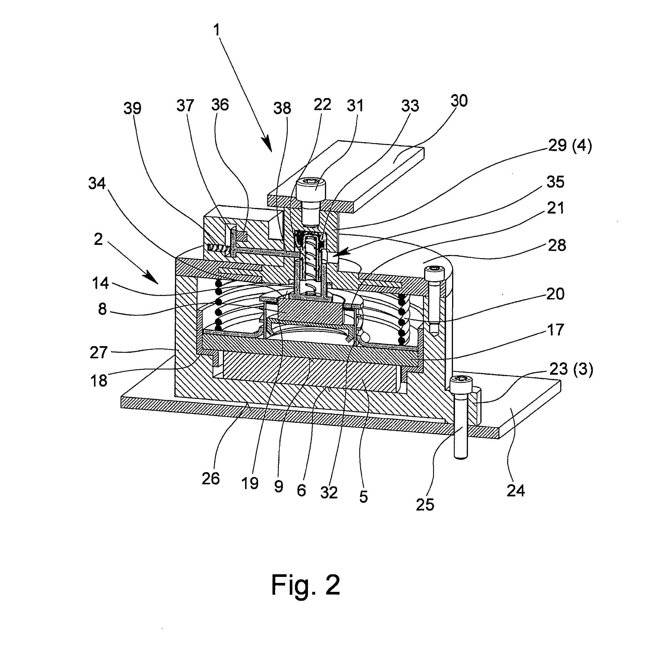
[0043]FIGS. 1 to 4 show a first preferred embodiment of the overvoltage protection device 1 in accordance with the invention with an essentially cylindrical housing 2 formed of metal, especially of aluminum, and with two terminals 3, 4 on the housing 2 for electrical connection of the overvoltage protection device 1 to the current path which is to be protected. Within the housing 2, there is a wafer-shaped varistor 5 as a first arrester. Moreover, between the two terminals 3, 4, in series with the varistor 5, there is a component in the housing 2 which is a gas-filled surge arrester 8 the exemplary embodiment according to FIGS. 1 to 4 and is a metal body 7 in the second exemplary embodiment according to FIGS. 6 and 7.

[0044]In the normal state of the overvoltage protection device 1 which is shown in FIGS. 1 and 3, the first terminal 3 is connected in an electrically conductive manner to the first connecting region 6 of the varistor 5 and the second terminal 4 is connected in an elect...


PUM


Abstract

A surge protection device having a housing, two connections for connection to a current path to be protected, and at least a first discharge conductor in the housing. In a normal state of the device, the first connection is electrically conductively connected to the first connection region of the discharge conductor, and the second connection is connected to the second connection region by at least one component. A metal safety element, which has two contact regions and a connecting region which connects the contact regions to one another, is arranged within the housing. The first contact region is electrically conductively connected to the second connection region and the second contact region is electrically conductively connected to the component in the normal state. The connecting region is a fuse by which brief pulse currents can be transmitted by the connecting region, whereas mains-frequency short-circuit currents overload the connecting region destroying it.

Description

BACKGROUND OF THE INVENTION[0001]1. Field of the Invention[0002]The invention relates to an overvoltage protection device with a housing, with two terminals for electrical connection of the overvoltage protection device to the current path which is to be protected, with at least one arrester, in particular a varistor, which is located within the housing, in the normal state of the overvoltage protection device the first terminal being connected in an electrically conductive manner to the first connecting region of the arrester and the second terminal being connected to the second connecting region of the arrester via at least one component.[0003]2. Description of Related Art[0004]Electrical circuits and systems normally work without perturbations with the voltage specified for them, the rated voltage. This does not apply when overvoltages occur. Overvoltages are all voltages which are above the upper tolerance limit of the rated voltage. They include mainly also the transient overvo...

Claims


Application Information

Patent Timeline
Patent Type & Authority Applications(United States)
IPC IPC(8): H01C7/12H02H9/04
CPCH01C7/12H02H9/04H01C7/126
Inventor DEPPING, CHRISTIAN
Owner PHOENIX CONTACT GMBH & CO KG
Learn More