
Method of evaluating image blur of optical film and optical film with reduced image blur

a technology of optical film and image blur, applied in the direction of photometry using electric radiation detectors, diffusing elements, instruments, etc., can solve the problems of reducing the lifespan due to deterioration, increasing the lifespan of the oled, and low power consumption

Active Publication Date: 2015-04-16
SAMSUNG CORNING PRECISION MATERIALS CO LTD +2
View PDF7 Cites 11 Cited by
  • Summary
  • Abstract
  • Description
  • Claims
  • Application Information

AI Technical Summary

Benefits of technology

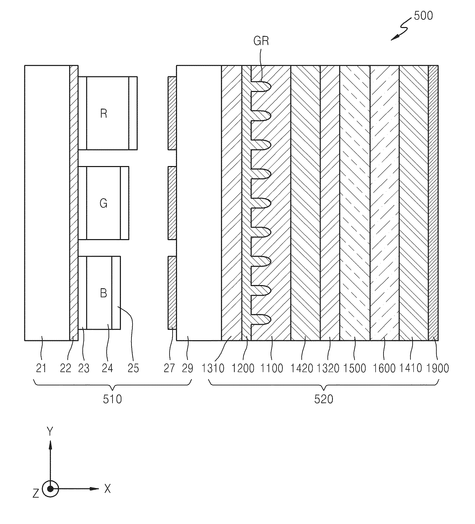
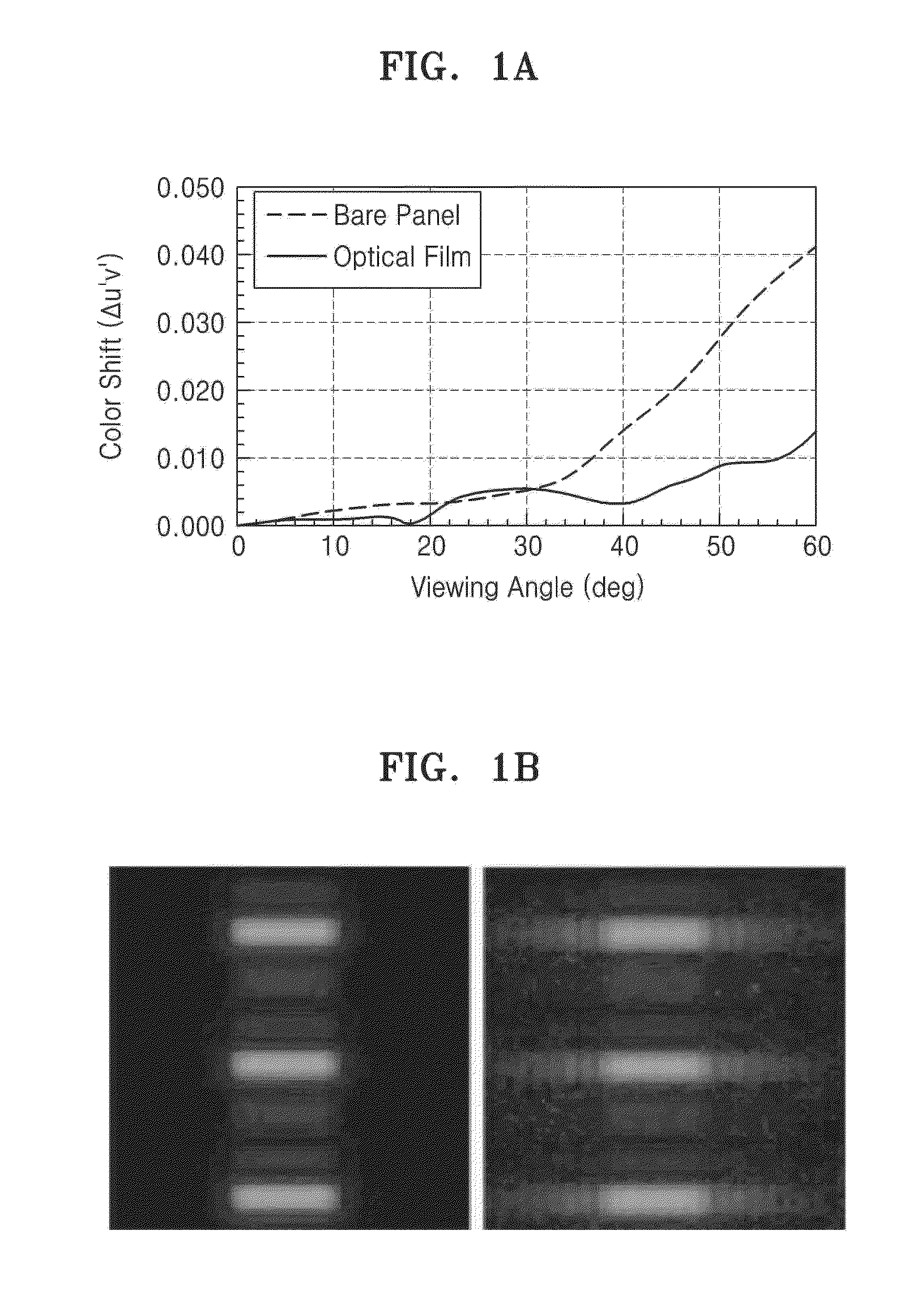
The patent describes an optical film that reduces color shifting in an OLED display, which can cause problems when viewing at certain angles. The film uses a pattern of high and low refractive index layers to create a lens that reduces color shifting and maintains high luminance in the center. The patent also includes a method for evaluating image blur of the optical film and how it can be used in OLED display to reduce image blur. Overall, the technical effect of the patent is to enhance the quality of OLED displays by reducing color shifting and improving image clarity.

Problems solved by technology

In the OLED, since a light-emitting material is an organic material, a problem of reduced lifespan due to deterioration is a critical issue in the development of OLED technology.
Furthermore, the increase of luminance may lead to low power consumption, thereby increasing lifespan of the OLED.
Therefore, image blur may occur.

Method used


Image

  • Method of evaluating image blur of optical film and optical film with reduced image blur
  • Method of evaluating image blur of optical film and optical film with reduced image blur
  • Method of evaluating image blur of optical film and optical film with reduced image blur

Examples


Embodiment Construction

[0058]The invention will now be described more fully hereinafter with reference to the accompanying drawings, in which various embodiments of the invention are shown. This invention may, however, be embodied in many different forms, and should not be construed as limited to the embodiments set forth herein. Rather, these embodiments are provided so that this disclosure will be thorough and complete, and will fully convey the scope of the invention to those skilled in the art. Like reference numerals refer to like elements throughout.

[0059]It will be understood that when an element is referred to as being “on” another element, it can be directly on the other element or intervening elements may be therebetween. In contrast, when an element is referred to as being “directly on” another element, there are no intervening elements present.

[0060]It will be understood that, although the terms “first,”“second,”“third” etc. may be used herein to describe various elements, components, regions,...


PUM

PropertyMeasurementUnit
refractive indexaaaaaaaaaa
thicknessaaaaaaaaaa
thicknessaaaaaaaaaa

Abstract

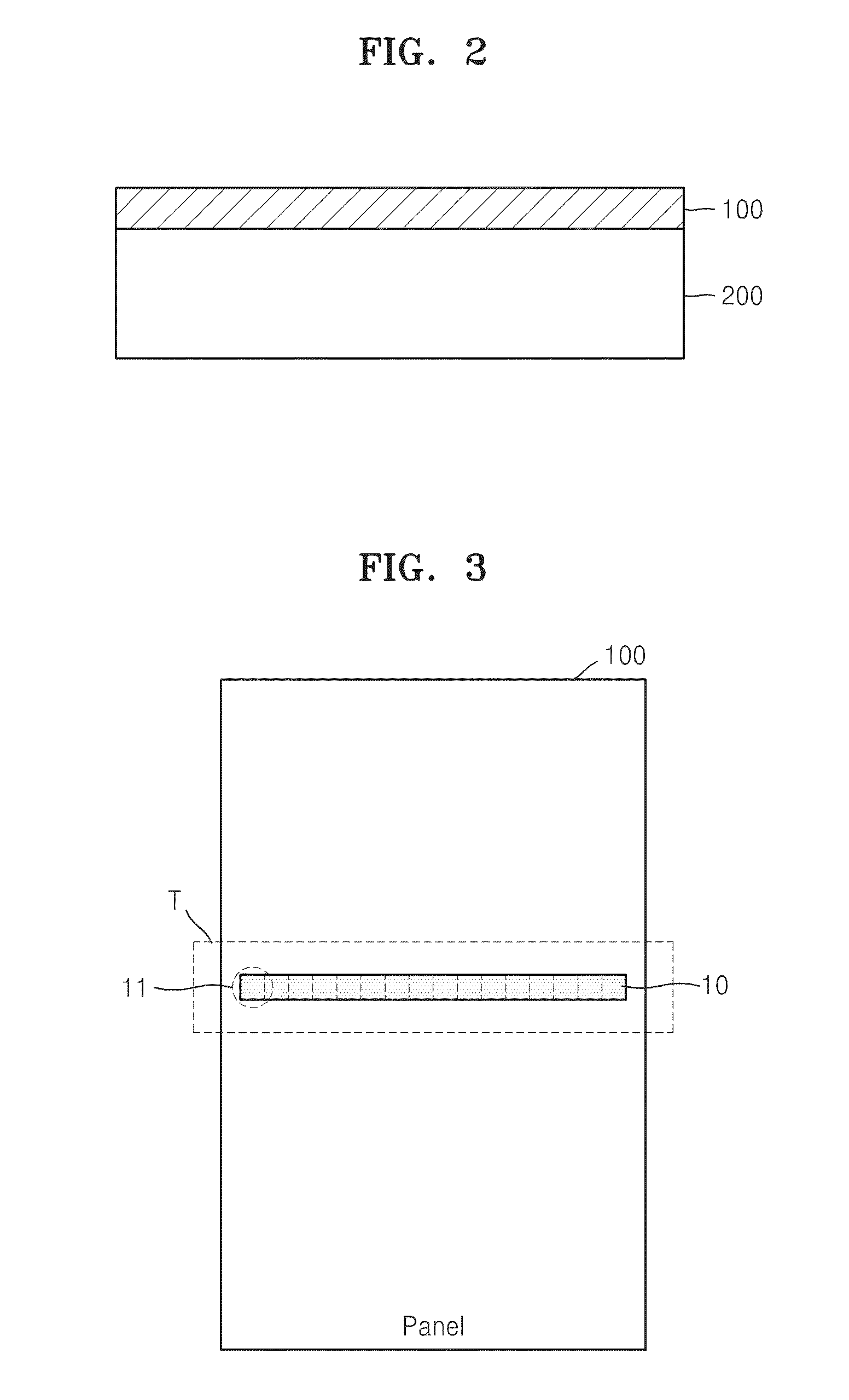
A method of evaluating an image blur of an optical film includes displaying a test pattern by driving an organic light-emitting display apparatus including the optical film, obtaining an image by capturing the test pattern using a digital camera, obtaining a spatial luminance distribution from the image, transforming the spatial luminance distribution into a sensation curve, and estimating a blur width from the sensation curve, where the blur width is a distance between peaks having negative minimum values, from among a plurality of peaks of the sensation curve.

Description

RELATED APPLICATION[0001]This application claims priority to Korean Patent Application No. 10-2013-0122820, filed on Oct. 15, 2013, and all the benefits accruing therefrom under 35 U.S.C. §119, the content of which in its entirety is herein incorporated by reference.BACKGROUND[0002]1. Field[0003]The disclosure relates to a method of evaluating image blur of an optical film, an optical film for reducing color shift with reduced image blur and an organic light-emitting display apparatus including the optical film.[0004]2. Description of the Related Art[0005]An organic light-emitting diode (“OLED”) typically includes an anode, an organic emission layer and a cathode. In such an OLED, when a voltage is applied between the anode and the cathode, holes are injected from the anode to the organic emission layer, and electrodes are injected from the cathode to the organic emission layer. The holes and electrons injected into the organic emission layer recombine in the organic emission layer ...

Claims


Application Information

Patent Timeline
Patent Type & Authority Applications(United States)
IPC IPC(8): H01L51/52G02B5/02H01L27/32G01N21/88
CPCH01L51/5275G01N21/8851G02B5/0278G02B5/021G02B5/0294H01L27/32G01N2021/8887G01J1/4209G02B5/0236G02B27/34H10K59/876H10K59/879G02B5/02H10K71/70H10K50/858H10K50/852
Inventor KIM, HYUNMINSHIN, YOUMINSHIM, HONGSHIKOH, YOUNGJEONG, CHULHOCHO, EUNYOUNG
Owner SAMSUNG CORNING PRECISION MATERIALS CO LTD
Learn More