Cuff for Accentuating Venous Flow

a venous flow and accentuation technology, applied in the medical field, can solve the problems of invasive venography, time-consuming, and ineffective venography in comparison to ultrasonic methods, and achieve the effect of reducing the risk of vascular disease, and reducing the safety of patients

Inactive Publication Date: 2015-04-02
MACHAN LINDSAY S +1
View PDF3 Cites 3 Cited by
  • Summary
  • Abstract
  • Description
  • Claims
  • Application Information

AI Technical Summary

Problems solved by technology

Current methods of using Doppler ultrasound imaging for diagnosing DVT requires the technician to use their hand to obstruct blood, which is cumbersome and can result in injury after repeated use.
Furthermore, the popular non-invasive method called impedance plethysmography has been shown to be ineffective in comparison to ultrasonic methods (Wells).
Venography, the current gold standard, is invasive, time consuming and requires exposure to ionizing radiation.

Method used


Image

  • Cuff for Accentuating Venous Flow
  • Cuff for Accentuating Venous Flow
  • Cuff for Accentuating Venous Flow

Examples


Embodiment Construction

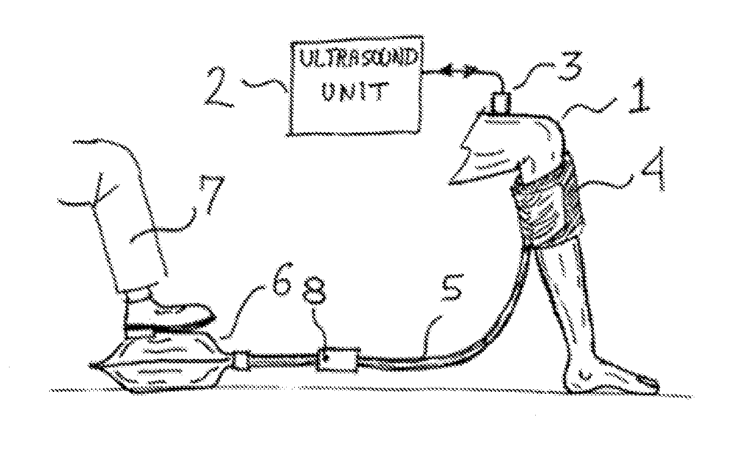
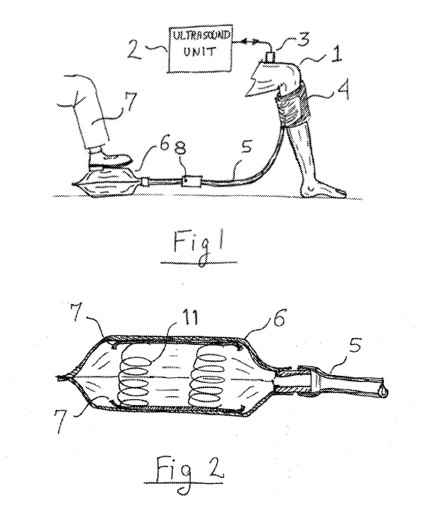
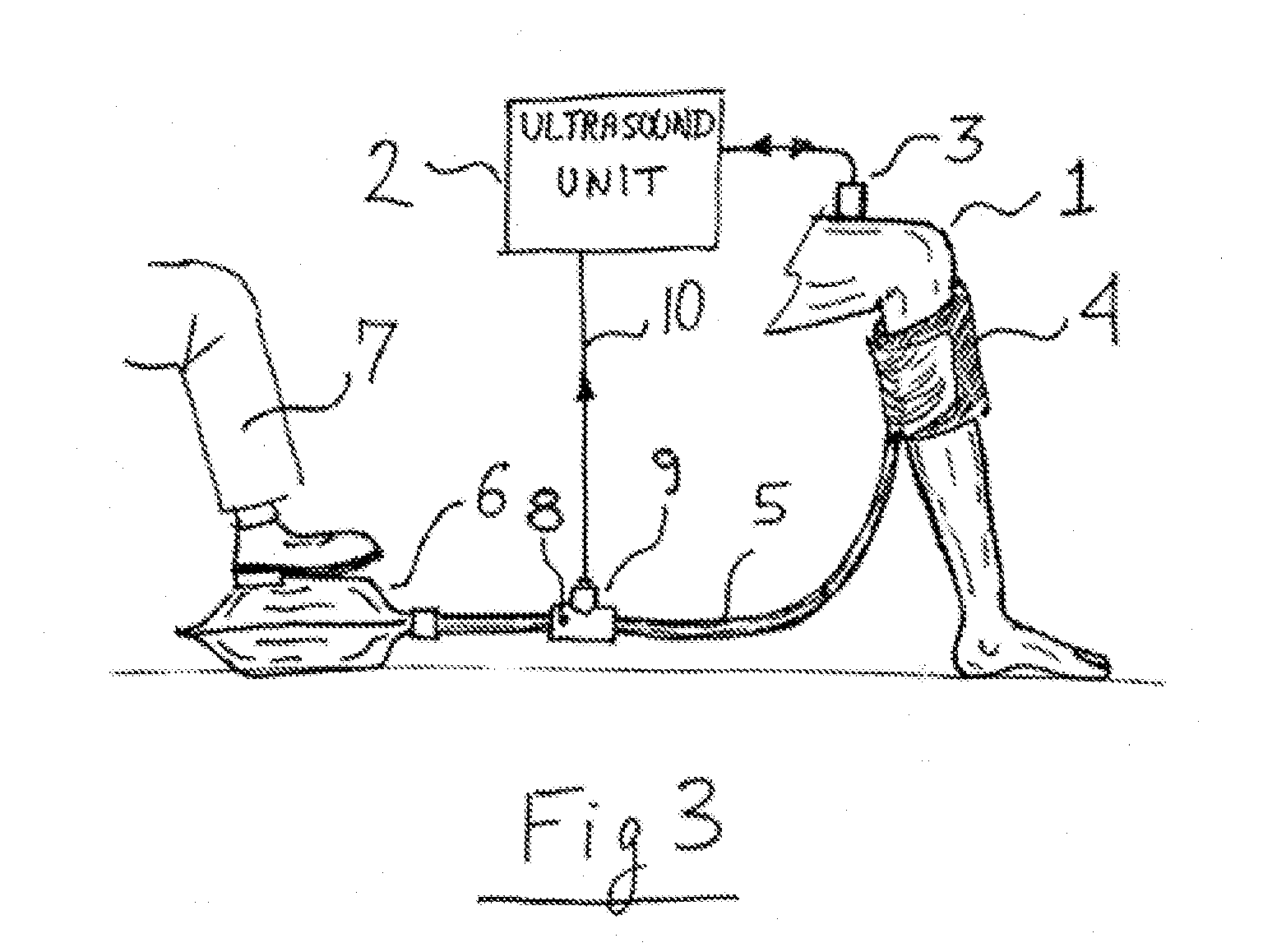
[0012]The disclosed invention is a system for rapidly squeezing a body part, such as a leg, and is shown in FIG. 1, to aid in the of diagnosis of vascular disorders. In order to monitor the condition of a patient's leg 1, the calf is momentarily squeezed by a pneumatic cuff 4 and the blood flow is monitored by an ultrasound machine 2 using a transducer 3. Similar ultrasonic procedures are well known in the art, for example for assessing DVT. Cuff 4 is connected to an air pump 6 via hose 5. Air pump 6 can be as simple as a rubber bag, bellows or piston pump. It can also be any type of motorized air pump. Hose 5 can also be connected to an external air supply. In such a case pump 6 is simply replaced by an air valve that can be electrically or mechanically operated. The advantage of using an external air supply is that the pressure generated by the cuff is always the same. When the user steps with foot 7 on air pump 6, cuff 4 inflates. When foot 7 is removed, cuff 4 deflates. Before t...


PUM


Abstract

A foot operated air pump rapidly inflates a pneumatic cuff wrapped around the leg of a patient. At the moment of inflation a pressure switch senses the increase in air pressure and sends a timing signal to an ultrasonic imaging system.

Description

FIELD OF INVENTION[0001]The invention is in the medical field, and in particular in the field of using ultrasound for evaluating vascular conditions such as DVT.BACKGROUND OF THE INVENTION[0002]In certain medical procedures it is desired to momentary squeeze the blood from one part of the patient's body and observe its flow. An example is the use of ultrasound to assess Deep Vein Thrombosis (DVT). Traditionally this is performed by a doctor or technician using one hand to squeeze the veins in the calf of the patient and using the other hand to position the ultrasound probe. This procedure is difficult to do as both probe positioning and squeezing have to be done at the same time. Furthermore, the ultrasonic scan has to be synchronized with the squeezing, requiring three events to take place at the same time. The physician or technician performing the procedure must stretch to restrict blood flow through the vein at the same time, which is very and can cause back strain in some peopl...

Claims


Application Information

Patent Timeline
Patent Type & Authority Applications(United States)
IPC IPC(8): A61B8/00A61B8/06
CPCA61B8/06A61B8/403A61B8/0891A61B8/4209A61B8/543
Inventor MACHAN, LINDSAY S.GELBART, DANIEL
Owner MACHAN LINDSAY S
Why Eureka
Try Eureka