
Adapter For Contacting Bus Bars

a technology for connecting cables and bus bars, which is applied in the direction of electrically conductive connections, coupling device connections, electrical apparatus, etc., can solve the problems of inability to ensure the security of connection, time-consuming and labor-intensive removal of cables, and inability to use suitable tools, etc., to achieve convenient wedging of individual lines of connecting cables, simple pulling out, and greater wedging

Inactive Publication Date: 2015-04-02
KLAUS BRUCHMANN
View PDF3 Cites 9 Cited by
  • Summary
  • Abstract
  • Description
  • Claims
  • Application Information

AI Technical Summary

Benefits of technology

The invention is a connecting structure that allows for reliable opening of the spring-terminal structure with a single actuation of the lever switch. The lever switch design ensures simultaneous contact between the spring terminals and the busbars, providing secure contacting between the busbar adapter and the connecting cable. The spring force for the contact action is set via the lever arm, ensuring easy switching of the lever switch by the user. The spring-terminal structure provides a holding force to keep the connecting cable in the adapter counter to a pulling force. The leaf spring and U-shaped contact connection secure the connecting cable in the busbar adapter with a simple pulling-out of the cable being impossible. The design allows for increased friction to prevent sliding of the poles out of the spring-terminal structure. Overall, the invention simplifies the connection process and ensures reliable security of the connecting cable.

Problems solved by technology

A further disadvantage of these conventional systems is that removing the cable likewise requires time and that often suitable tools are required for this.
Screw-type connections further exhibit the disadvantage that such connections can become loose over time and thus a secure connection often cannot be guaranteed over a longer period of time.

Method used


Image

  • Adapter For Contacting Bus Bars
  • Adapter For Contacting Bus Bars
  • Adapter For Contacting Bus Bars

Examples


Embodiment Construction

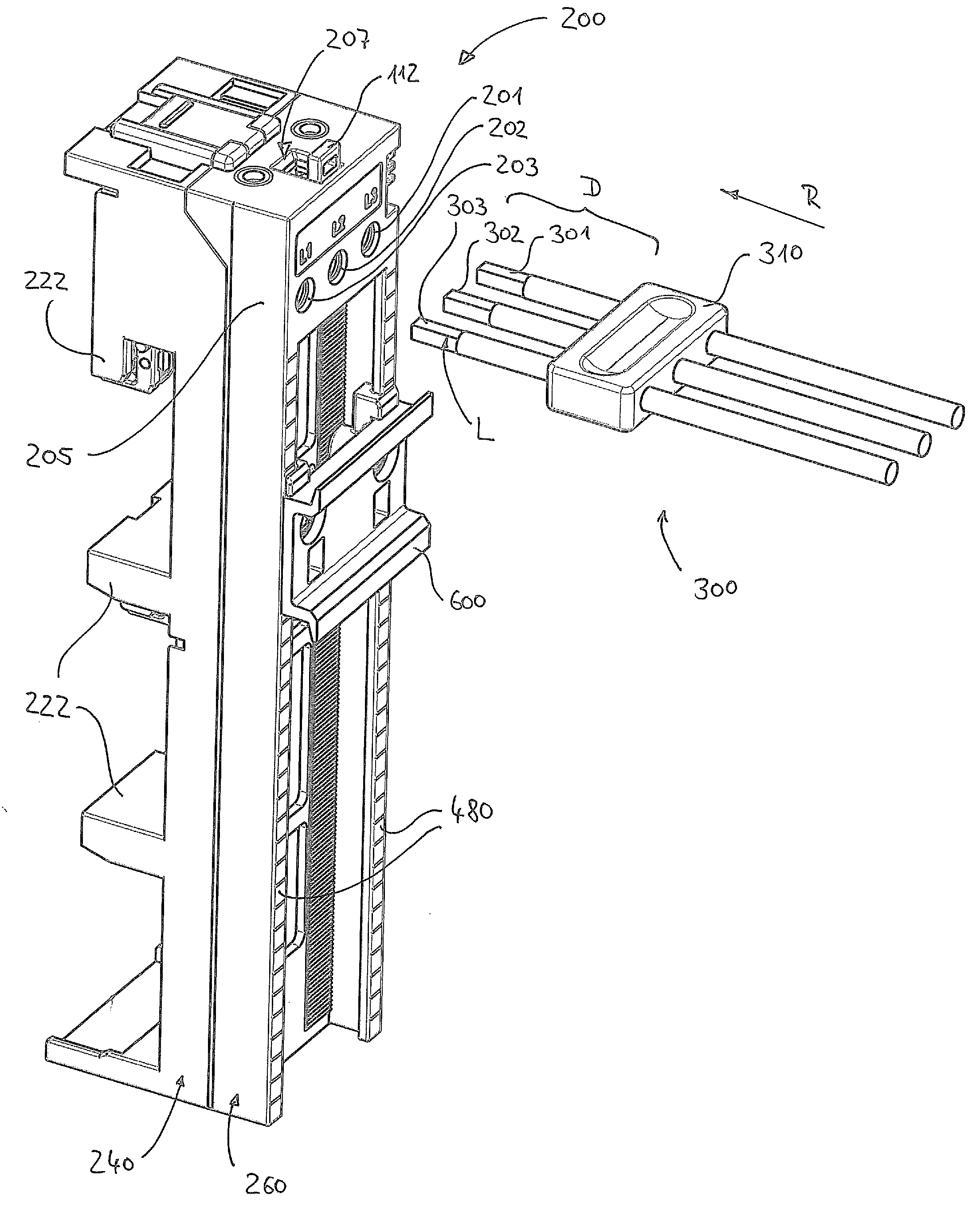
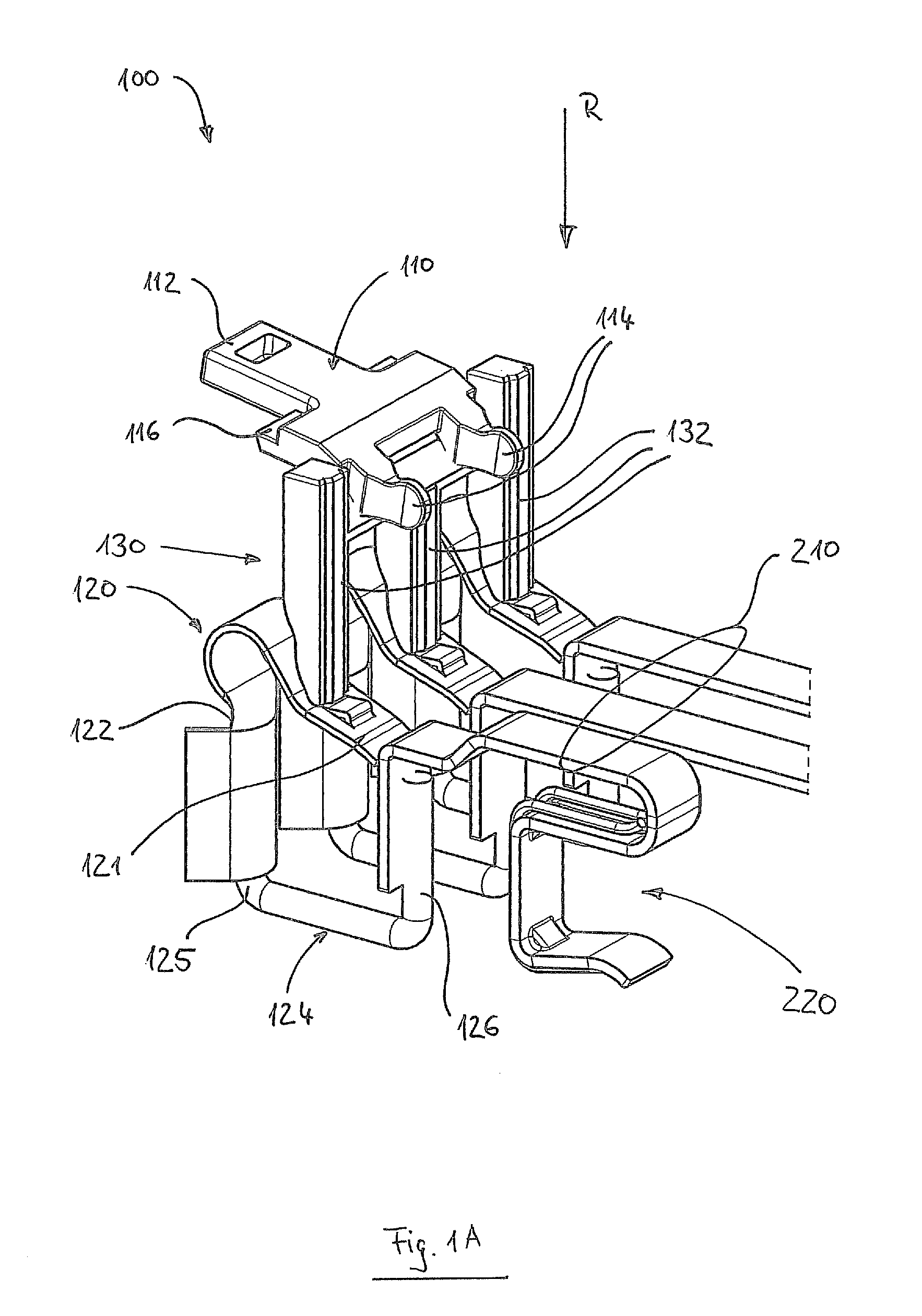
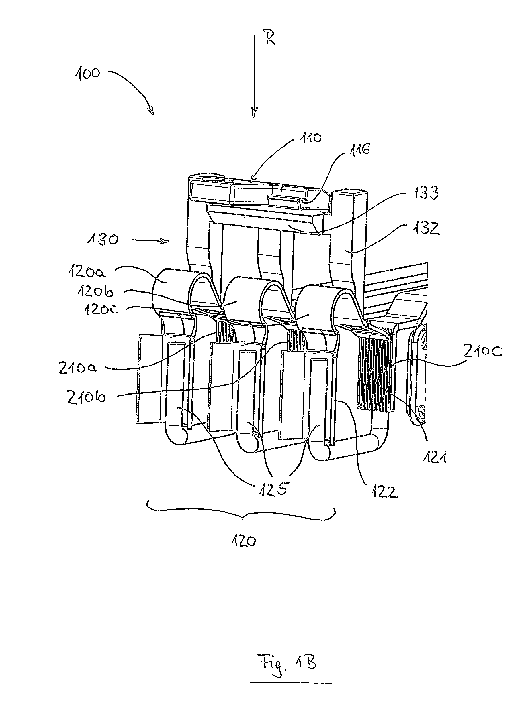
[0026]FIGS. 1A and 1B show a cable-connecting device 100 that can be inserted into an adapter, and FIGS. 1C and ID show an enlarged detail of the adapter 200 with an inserted cable-connecting device 100. The connecting cable is described in more detail below using FIGS. 2A and 2B, and further details of the adapter can be gathered from the cross-sectional views of FIGS. 3A-3I.

[0027]The cable-connecting device 100 exhibits a lever switch 110, a connecting structure 130, and in this exemplary embodiment three spring terminals as spring-terminal structure 120. The lever switch 110 exhibits a lever arm 112 and opposite a propping structure or a propping section 114, a fulcrum P (that is concealed in the figure) contacting the connecting structure 130 between the lever arm 112 and the propping structure 114. The propping structure 114 for examples serves as a pivot for the lever arm 112, so that the propping section 114 rotates relative to a housing when the lever switch 110 is actuated,...


PUM

PropertyMeasurementUnit
spring forceaaaaaaaaaa
tensionaaaaaaaaaa
pulling forceaaaaaaaaaa

Abstract

An adapter for contacting busbars with a multi-pole connecting cable is disclosed with at least two contact connections for at least two busbars; a housing having holding means; and a cable-connecting device that is secured in the housing by the holding means. The cable-connecting device has: a lever switch; a spring-terminal structure; and a connecting structure. The lever switch has a fulcrum onto which a leverage acts when the lever switch is actuated. The spring-terminal structure provides a spring force for establishing an electrical contact between one of the plurality of poles and one of the at least two contact connections by the spring force after inserting the connecting cable. The connecting structure is arranged between the lever switch and the spring-terminal structure and is designed for transferring the leverage from the lever switch to the spring-terminal structure and to tension the spring-terminal structure counter to the spring force.

Description

FIELD OF THE INVENTION[0001]The present invention relates to an adapter for contacting busbars (busbar adapter) and in particular an adapter for contacting busbars having a multi-pole connecting cable, thus achieving simultaneous and joint contacting of all poles (lines) of the multi-pole connecting cable.BACKGROUND OF THE INVENTION[0002]Busbar adapters are in particular suitable for fastening fuse systems, switch-fuse units etc., but also for all other electrical installation appliances on electrical busbar systems that are used for power supply, in particular three-phase busbar systems being used.[0003]Such busbar adapters are contacted by means of a multi-pole connecting cable that exhibits a plurality of lines (or poles). For example, a three-phase connecting cable exhibits a single line for each phase, in conventional systems each line being fastened individually to the corresponding cable terminal. For this purpose, for example screw, solder, or weld connections have been used...

Claims


Application Information

Patent Timeline
Patent Type & Authority Applications(United States)
IPC IPC(8): H01R13/629H01B17/38H01R4/48
CPCH01R13/62933H01B17/38H01R4/489H01R4/48H01R2105/00H01R25/145H02B1/21H01R4/4852H01R4/4828H01R4/4821H01R4/4837
Inventor BRUCHMANN, KLAUS
Owner KLAUS BRUCHMANN
Learn More