Structure for Mounting Retrofit Part to Cladding Member

Active Publication Date: 2015-03-26
YAZAKI CORP
View PDF7 Cites 20 Cited by
  • Summary
  • Abstract
  • Description
  • Claims
  • Application Information

AI Technical Summary

Benefits of technology

The invention aims to prevent displacement and turning of a retrofit part when mounted on a cladding member. The solution involves adding uneven portions or spike-shaped portions on the retrofit part surface to interact with the cladding member. This prevents the retrofit part from causing a turn or displacement. The invention also includes securing a bitable member or friction force enhancing member to the cladding member to further prevent displacement. The bitable member can be any material such as tube, resin layer, or coating that can interact with the uneven portions or spike-shaped portions on the retrofit part. This results in a more secure mounting of the retrofit part without compromising workability.

Problems solved by technology

If the clamp has caused a turn or positional displacement, a problem which will arise is that the clamp needs to be returned to its original position before being fixed to the vehicle body.
Specifically, there is a problem of a potential to deteriorate workability with regard to mounting a related-art clamp (a retrofit part).

Method used


Image

  • Structure for Mounting Retrofit Part to Cladding Member
  • Structure for Mounting Retrofit Part to Cladding Member
  • Structure for Mounting Retrofit Part to Cladding Member

Examples


embodiments

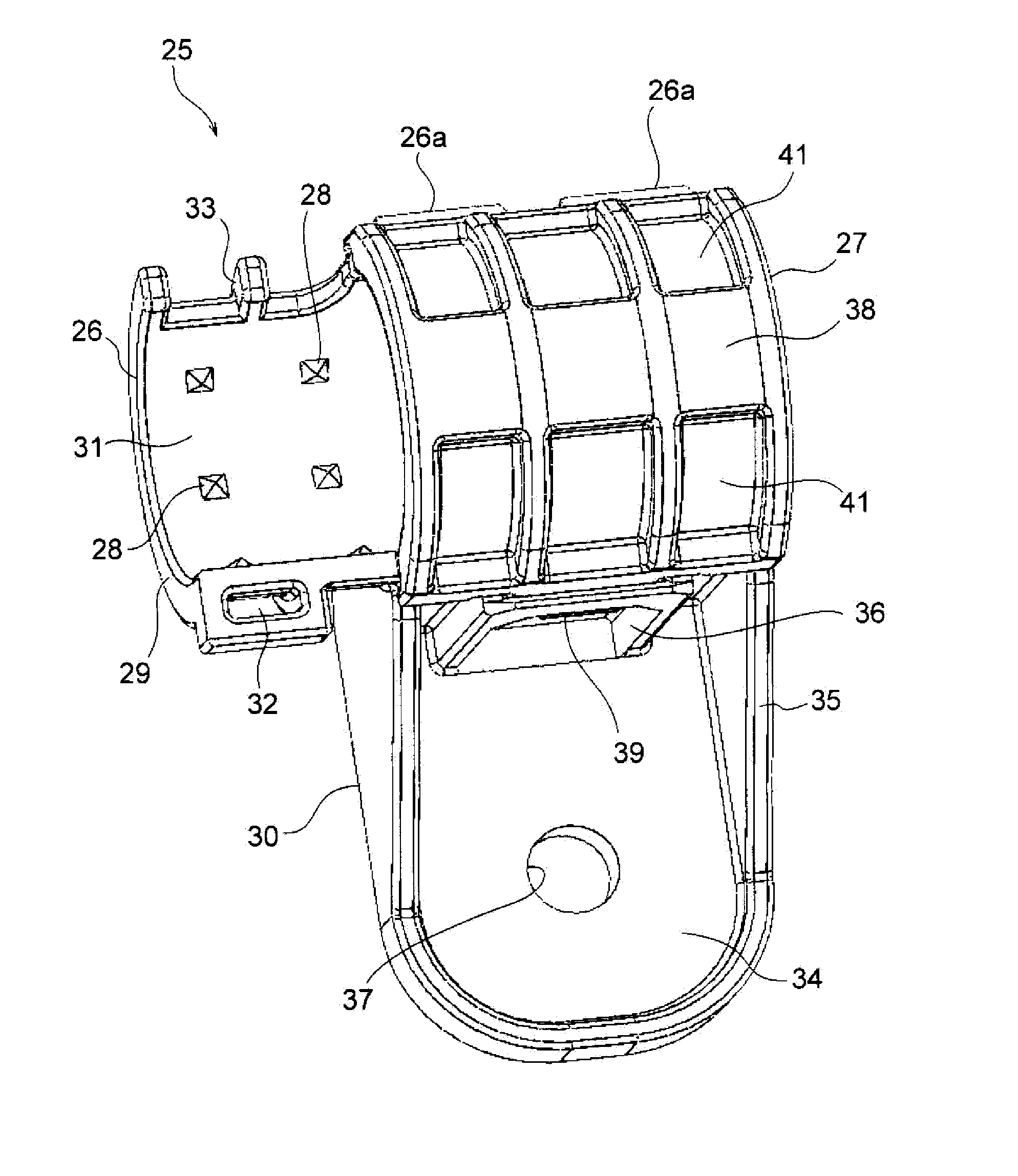
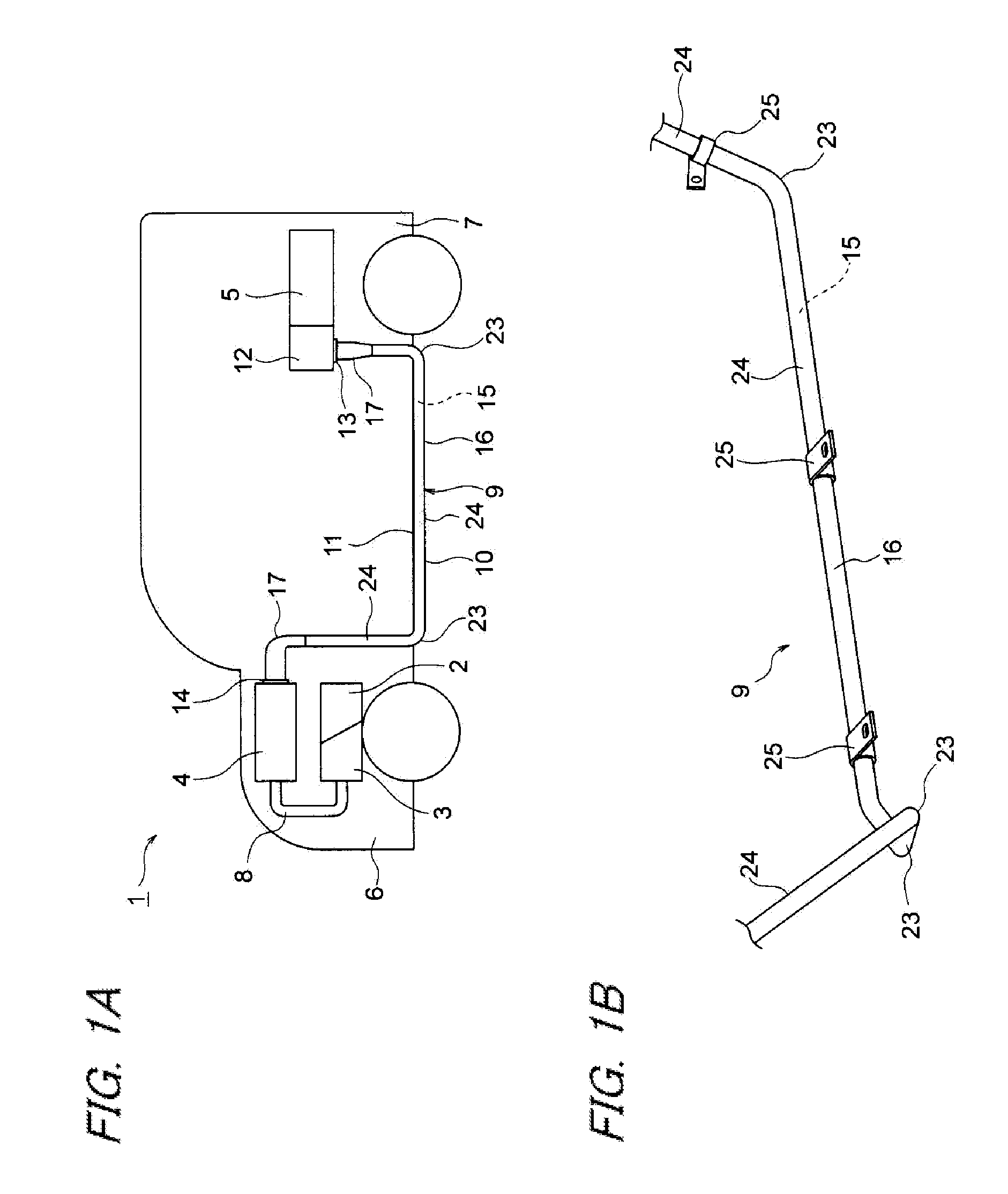
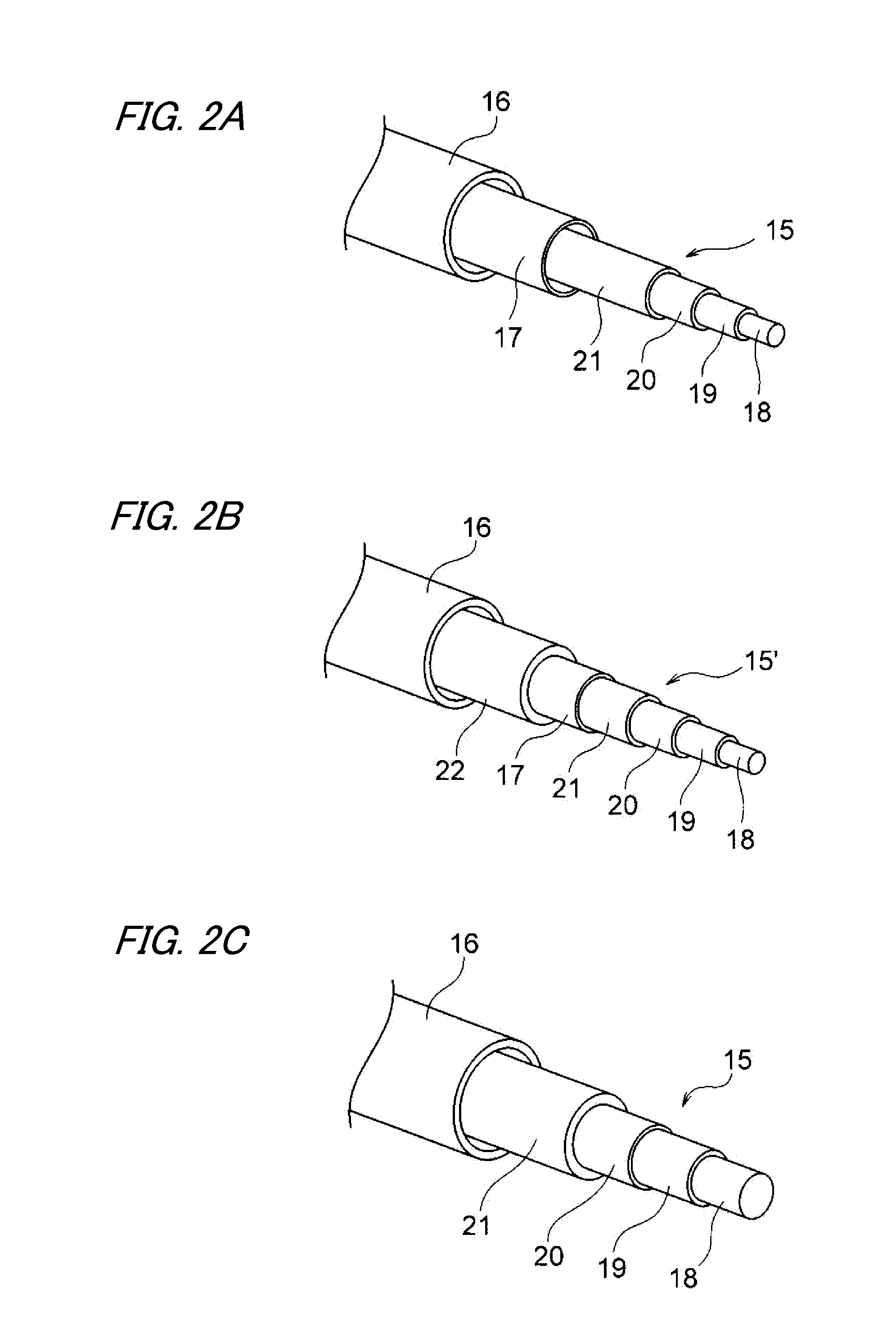
[0035]Embodiments are hereunder described by reference to the drawings. FIGS. 1A and 1B are drawings according to one embodiment of the invention, wherein FIG. 1A is a drawing showing a state of a routed wire harness and FIG. 1B is a drawing showing a state in which a cladding member is mounted to a clamp (a retrofit part). FIGS. 2A to 2C are structural diagrams of conductive paths in the wire harness. FIG. 3 and FIGS. 4A and 4B are drawings of a clamp that is to serve as a first embodiment. FIG. 5 and FIGS. 6A and 6B are drawings of a clamp that is to serve as a second embodiment. FIG. 7 and FIGS. 8A and 8B are drawings of a clamp that is to serve as a third embodiment. FIGS. 9A to 9E are perspective views of a cladding member of the wire harness.

[0036]In the embodiments, the invention is presumed to be adopted in connection with a wire harness routed in a hybrid automobile (which can also be a pure electric vehicle or a common automobile).

[0037]In FIGS. 1A and 1B, reference numera...


PUM


Abstract

To provide a structure for mounting a retrofit part to a cladding member that can prevent the retrofit part from causing a turn or positional displacement. A clamp includes a clamp base and a clamp cover continuous to the clamp base by a hinge. The clamp has spike-shaped portions. The spike-shaped portions are formed and placed on both a mount surface of the clamp base and a mount surface of the clamp cover. The spike-shaped portions are an area that prevents the clamp from causing a turn or positional displacement, and each protrusively formed substantially into a pyramid shape with a pointed end. The spike-shaped portions are formed as an area that bites into an exterior surface of a cladding member and that resists external force, such as vibrations, when the clamp is mounted.

Description

CROSS REFERENCE TO RELATED APPLICATIONS[0001]This application is a continuation of PCT application No. PCT / JP2013 / 065899, which was filed on Jun. 3, 2013 based on Japanese patent application (patent application 2012-126685) filed on Jun. 4, 2012, whose contents are incorporated herein by reference. Also, all the references cited herein are incorporated as a whole.BACKGROUND OF THE INVENTION[0002]1. Technical Field[0003]The invention relates to a structure for mounting, to a cladding member that makes up a wire harness, a retrofit part to be retrofitted to the cladding member.[0004]2. Background Art[0005]An electrical connection is established between a battery and an inverter unit in; for instance, a hybrid automobile and a pure electric vehicle, by means of a high voltage wire harness. The wire harness includes a high voltage electric cable that is to serve as a high voltage conductive path and a cladding member that accommodates the high voltage electric cable.[0006]In Patent Docu...

Claims


Application Information

Patent Timeline
IPC IPC(8): H02G3/04F16B2/06B60R16/02
CPCH02G3/0406F16B2/06B60R16/0215F16L3/1083F16L3/1211F16L55/035
Inventor YOSHIDA, HIROYUKITOHYAMA, EIICHIOGA, TATSUYAINAO, SHINICHISUGURO, MASAAKI
Owner YAZAKI CORP
Why Eureka
Try Eureka