
Power transmission apparatus for vehicle

Active Publication Date: 2015-03-26
TOYOTA JIDOSHA KK
View PDF8 Cites 29 Cited by
  • Summary
  • Abstract
  • Description
  • Claims
  • Application Information

AI Technical Summary

Benefits of technology

The present invention is a power transmission apparatus for vehicles that reduces the noise from gears. It is designed to prevent rattling noise that occurs when driving through a spline-fitting section in a torque transmission path. Overall, this invention aims to improve the performance and comfort of vehicle transmissions.

Problems solved by technology

Consequently, the torque output by the drive source (a fluctuation in rotation) may cause generation of the noise in the gear pair, which is arranged upstream of the spline-fitting section in the torque transmission path.
However, since an elastic force of rubber or a resin varies by temperature, the stable shock-absorbing effect may not be obtained.
Thus, the stable shock-absorbing effect may not be obtained.

Method used


Image

  • Power transmission apparatus for vehicle
  • Power transmission apparatus for vehicle
  • Power transmission apparatus for vehicle

Examples


first embodiment

[0068]As described above, according to the spline positioning mechanism 200 of the first embodiment, effects, which will be listed below, can be obtained.

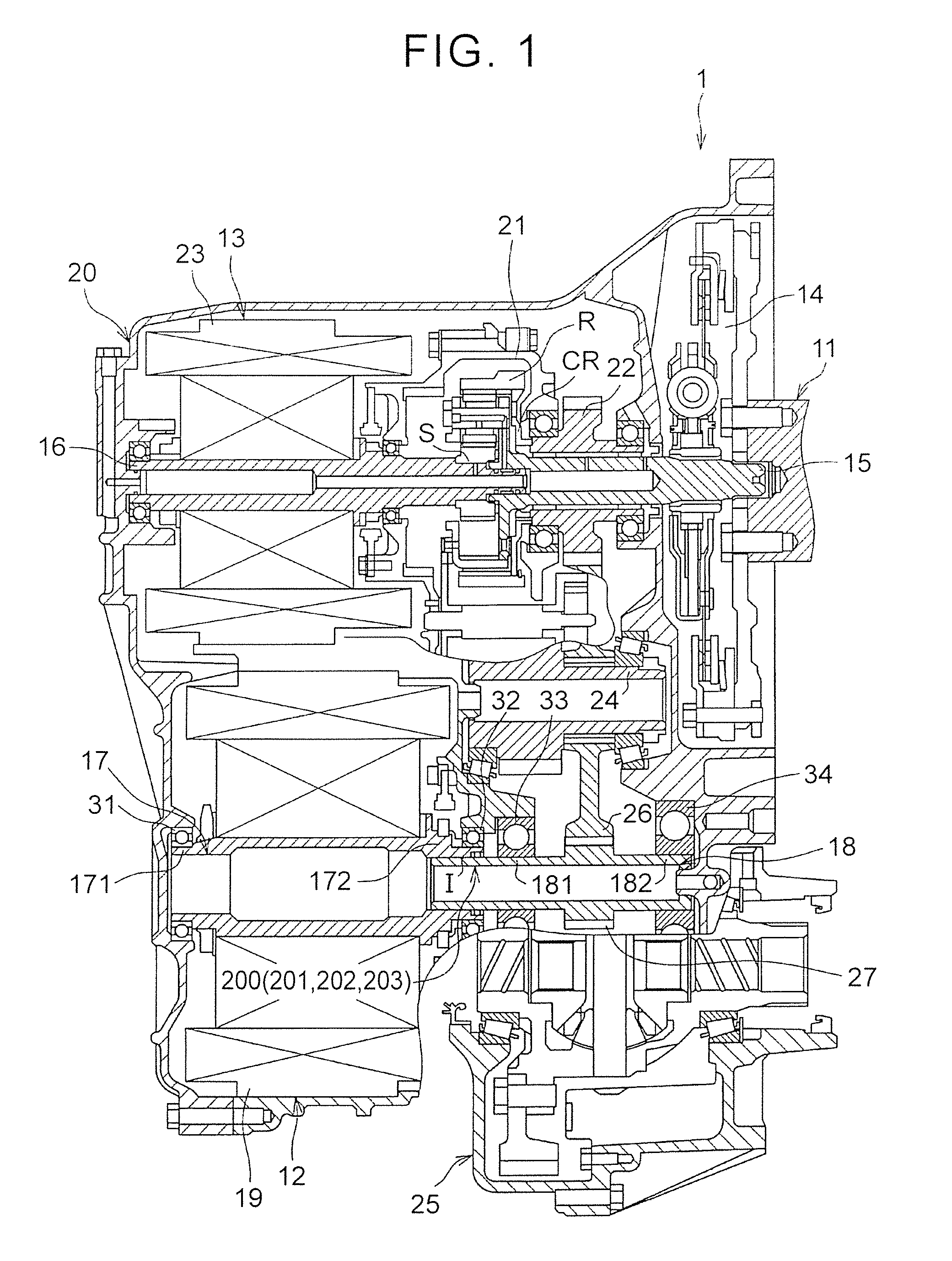
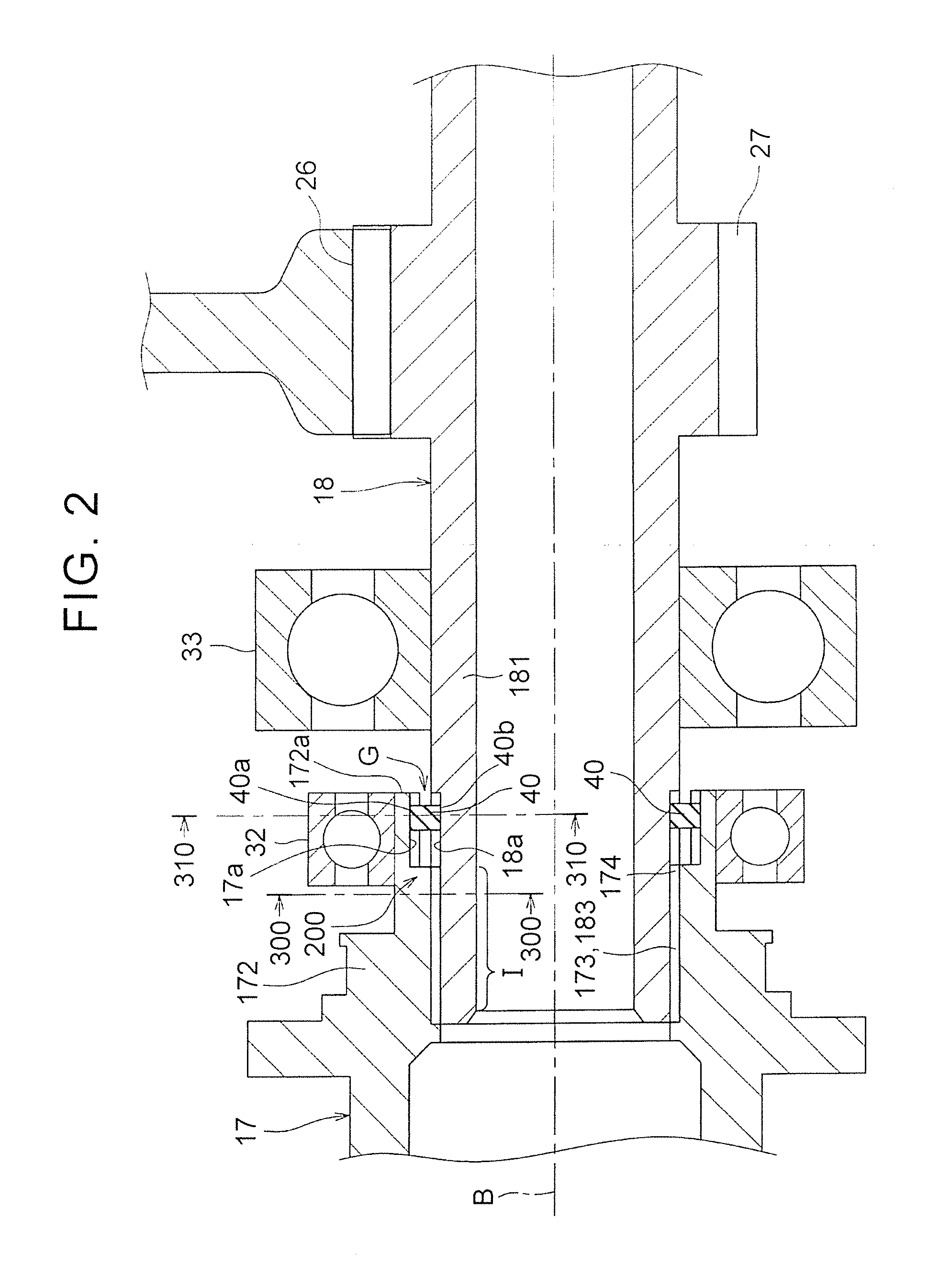
[0069]In the first embodiment, as described above, the key section 40 is arranged to determine the positions in the rotational direction of the inner spline 173 of the rotor shaft 17 in the motor 12 and the outer spline 183 of the drive shaft 18 to the specified positions, and applies the elastic force in the rotational direction to the rotor shaft 17 of the motor 12 and the drive shaft 18 such that the rotor shaft 17 and the drive shaft 18 are restored to the specified positions by the key section 40. Accordingly, when the motor 12 outputs torque, the key section 40 is bent and deformed in the rotational direction in conjunction with transmission of the torque by the rotor shaft 17 of the motor 12, and the inner spline 173 of the rotor shaft 17 in the motor 12 and the outer spline 183 of the drive shaft 18 abut against each other....

second embodiment

[0077]In the spline positioning mechanism 201 as shown in FIG. 8, a key with a ring (positioning member) 50 is arranged between the rotor shaft 17 of the motor 12 and the drive shaft 18. As shown in FIG. 9 and FIG. 10, the key with a ring 50 has a key section (the shock-absorbing section) 51 that is formed of an elastic member and a ring section 52. The key section 51 has a rectangular shape that extends along the radial direction. The ring section 52 holds the key section 51 between portions thereof. The ring section 52 has the shock-absorbing effect with respect to the thrust direction (axial direction).

[0078]As shown in FIG. 11, a specified space is provided between an outer end 51a of the key section 51 of the key with a ring 50 and the positioning member attachment section 17a of the other end 172 (see FIG. 8) of the rotor shaft 17. Meanwhile, a specified space is provided between an inner end 51b of the key section 51 of the key with a ring 50 and the positioning member attac...

third embodiment

[0093]As shown in FIG. 13, in the spline positioning mechanism 202 a key with a ring (positioning member) 60 is arranged between the rotor shaft 17 of the motor 12 and the drive shaft 18. As shown in FIG. 14 and FIG. 15, the key with a ring 60 has four key sections (shock-absorbing sections) 61, each of which is formed of an elastic member, and a ring section 62. The four key sections 61 are formed at equal angular intervals, and each have a rectangular shape that extends outward from the ring section 62. The ring section 62 has a circular shape so as to connect the four key sections 61. The ring section 62 has the shock-absorbing effect with respect to the thrust direction (axial direction).

[0094]As shown in FIG. 16, a specified space is provided between an outer end 61a of the key section 61 of the key with a ring 60 and the positioning member attachment section 17a of the other end 172 of the rotor shaft 17. Meanwhile, an inner peripheral surface 62a of the ring section 62 of th...


PUM


Abstract

A power transmission apparatus includes a first / second / third rotary shaft, and a positioning member. The first rotary shaft is connected to an output shaft of a drive source. The second rotary shaft is spline-fitted to a rotary shaft of an electric motor. The third rotary shaft is connected to the first rotary shaft and the second rotary shaft. The positioning member is configured to apply an elastic force in a rotational direction to the rotary shaft and the second rotary shaft in a portion where the rotary shaft and the second rotary shaft overlap each other; set each of a position in the rotational direction of a spline of the rotary shaft of the electric motor and a spline of the second rotary shaft to a specified position, and applies the elastic force in the rotational direction to the rotary shaft and the second rotary shaft.

Description

INCORPORATION BY REFERENCE[0001]The disclosure of Japanese Patent Application No. 2013-197763 filed on Sep. 25, 2013 including the specification, drawings and abstract is incorporated herein by reference in its entirety.BACKGROUND OF THE INVENTION[0002]1. Field of the Invention[0003]The present invention relates to a power transmission apparatus for a vehicle.[0004]2. Description of Related Art[0005]A mechanism capable of reducing noise in a spline-fitting section that connects a rotary shaft of an electric motor and a drive shaft (rotary shaft) has been known (see Japanese Patent Application Publication No. 2011-214646 (JP 2011-214646 A), for example).[0006]The mechanism that is disclosed in JP 2011-214646 A above includes a drive source (an engine), a generator, and an electric motor as primary components. The rotary shaft of the electric motor is spline-fitted to the drive shaft that is coaxially arranged. The drive shaft is indirectly connected to the drive source. The drive sha...

Claims


Application Information

Patent Timeline
IPC IPC(8): B60K1/00F16H3/08
CPCF16H3/08B60K1/00F16H3/727F16H2037/0866F16H2200/2005F16D1/10F16D2001/103F16D2300/22Y10T74/19233F16D3/68
Inventor ISOMURA, HARUO
Owner TOYOTA JIDOSHA KK
Learn More