
System AMD method for bone fusing implants and implant insertion tools

a bone fusing and implant technology, applied in the field of system and method of bone fusing implants and implant insertion tools, can solve the problems of stress on this weight-bearing area of the pelvis and spine, poor patient outcome, permanent scarring and pain that can be more sever

Active Publication Date: 2015-03-19
KIC VENTURES LLC
View PDF3 Cites 44 Cited by
  • Summary
  • Abstract
  • Description
  • Claims
  • Application Information

AI Technical Summary

Benefits of technology

The present invention relates to a system and method for fusing two adjacent stacked bones, particularly for sacroiliac joint fusion. The invention features bone fusing implants and insertion tools that are designed to facilitate the process of fusing the bones. The technical effects of the invention include improved bone fusing implants and insertion tools that make the bone fusing process more efficient and effective.

Problems solved by technology

These joints are important in transferring the load of the upper body to the lower body, supporting the entire weight of the upper body when we are erect, which in turn results in stress to this weight-bearing area of the pelvis and spine.
There is increasing concensus among surgeons that there is a need to develop devices, instruments, and methods to limit the size of the incision, extensive muscle stripping, prolonged retraction of muscles for visualization, avoidance of neural tissue retraction and injury, and denervation and devascularization that are known to contribute to poorer patient outcome after traditional open surgeries to treat pathologies deep within the body.
In many cases these complications lead to permanent scarring and pain that can be more severe than the pain from the initial ailment.

Method used


Image

  • System AMD method for bone fusing implants and implant insertion tools
  • System AMD method for bone fusing implants and implant insertion tools
  • System AMD method for bone fusing implants and implant insertion tools

Examples


Embodiment Construction

[0040]The present invention relates to a system and a method for bone fusing implants and implant insertion tools, and more particularly to bone fusing implants that are used for sacroiliac joint fusion.

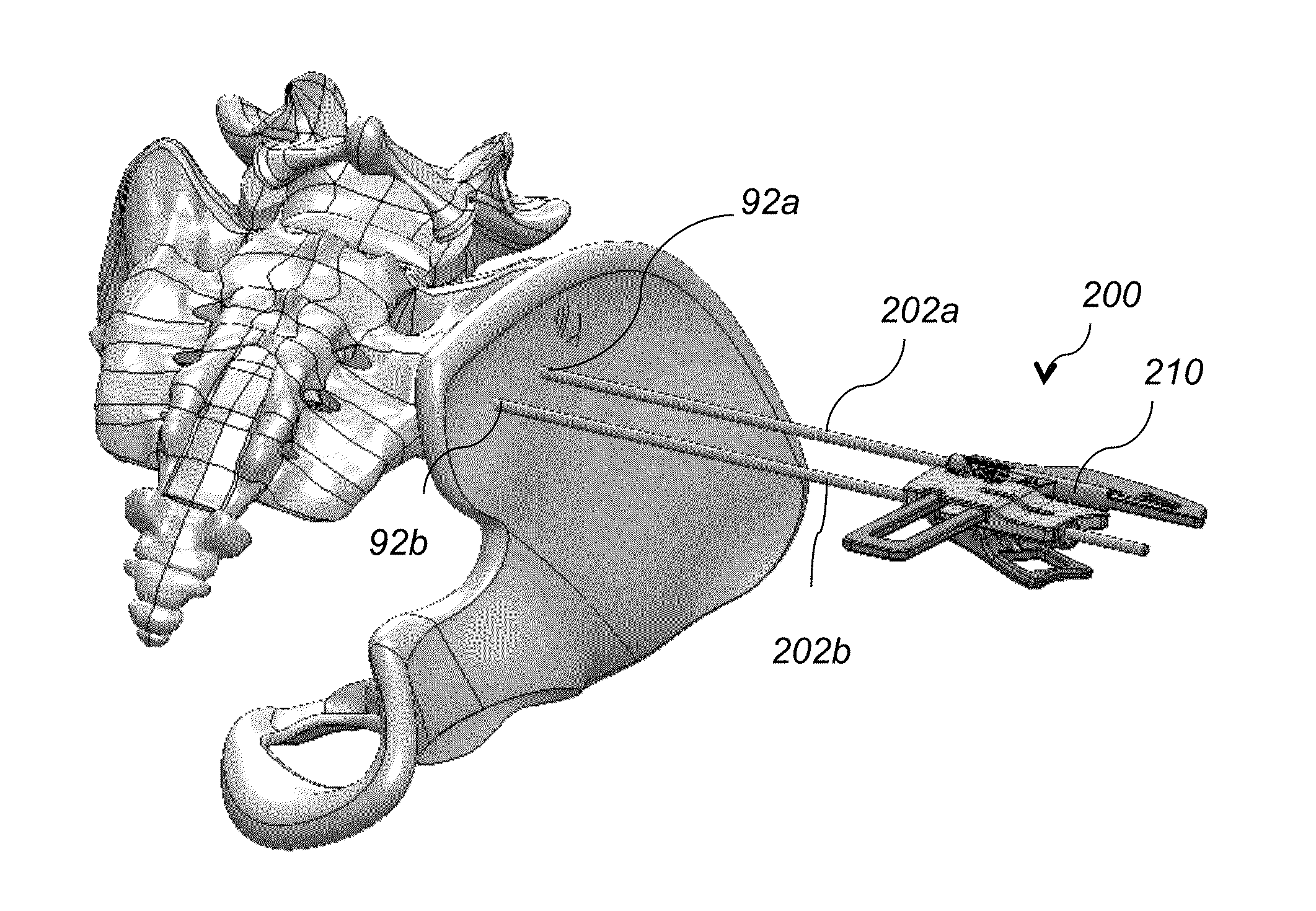
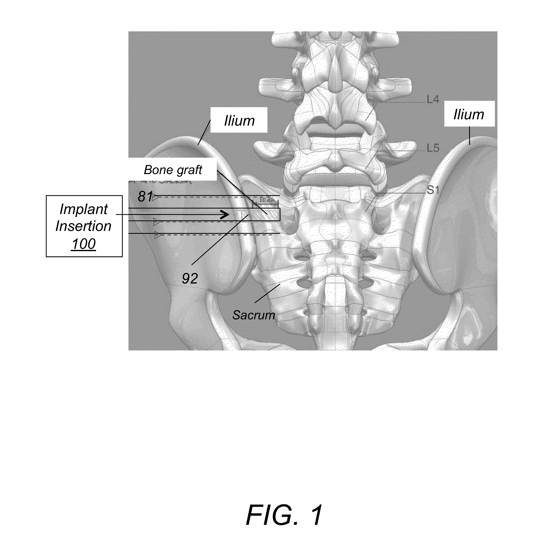
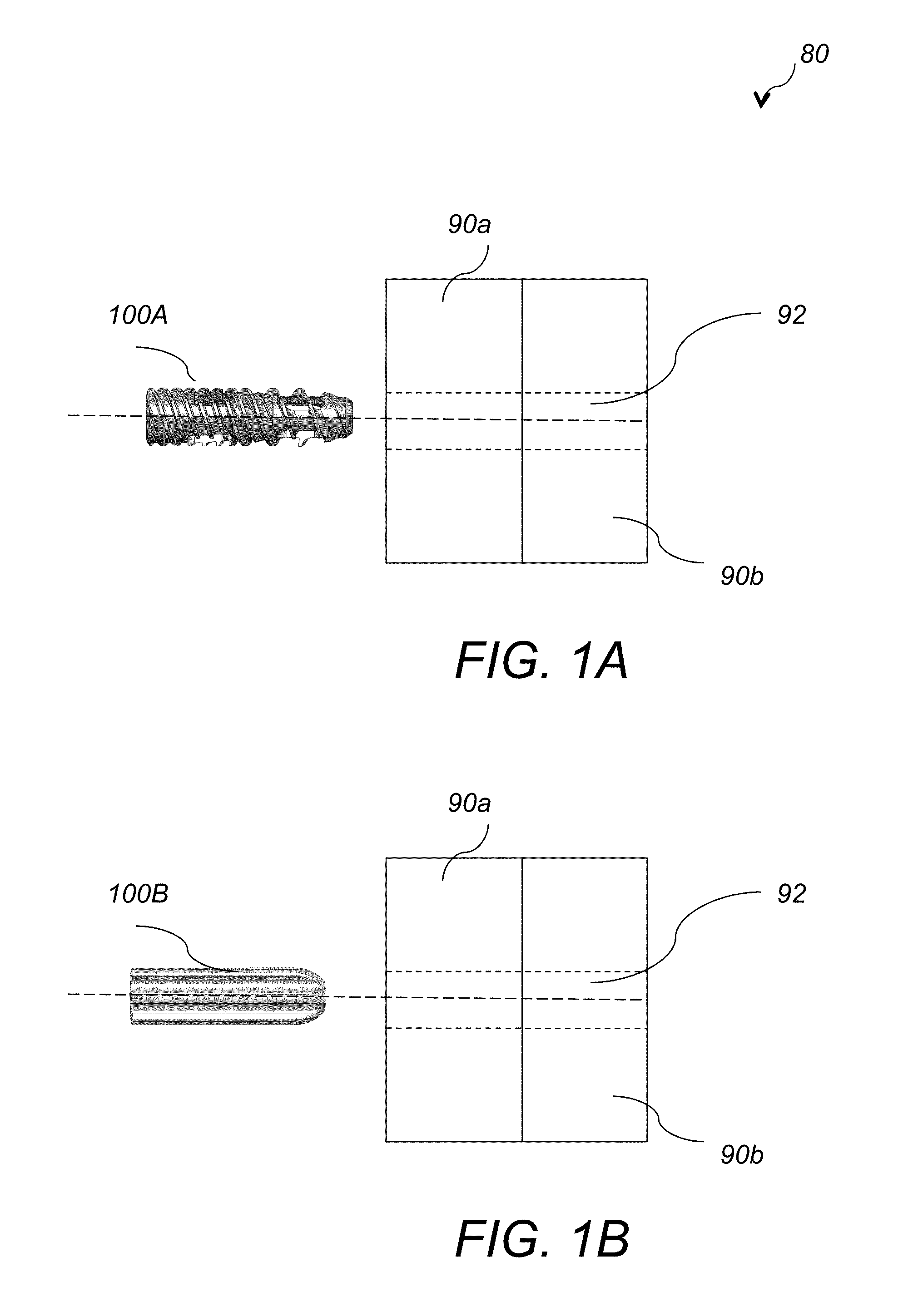
[0041]Referring to FIG. 1, in SIJF surgery one or more openings 92 are formed along the arrow direction 81 and bone fusing implants 100 are inserted in the formed openings 92. Referring to FIG. 1A, bone fusing implant 100A is inserted in opening 92 that is formed through two stacked adjacent bone members 90a and 90b. In one example, bone member 90a is primarily a cortical (compact) bone and bone member 90b is in majority a cancellous (porous) bone. Referring to FIG. 2A and FIG. 2B, bone implant 100A includes a cylindrical hollow threaded body 110 that has six oval shaped openings 112a, 112b, 112c, 112d, 112e, 112f, a through opening 122 that extends the entire length of the implant and a first segment 130 with cortical threads 132 and a second segment 140 with cancellous threads 142....


PUM


Abstract

A method for fusing two adjacent stacked bones includes the following. First, inserting first and second pins into first and second locations of a first surface of one of the two adjacent stacked bones, respectively. Next, inserting a dilator over each of the first and second pins to dilate tissue around the first and second pins. Next, inserting a tissue protector over the dilator and removing the dilator. Next, inserting a cannulated drill through the tissue protector over each of the first and second pins and drilling first and second openings in the first and second locations, respectively, wherein the first and second opening extend through the two adjacent stacked bones. Next, tapping threads in the first opening and inserting a first bone fusing implant in the first opening, wherein the first bone fusing implant comprises threads configured to engage the threads of the first opening. Next, impacting a broach into the second opening to generate a pattern corresponding to a pattern of a second bone fusing implant and then inserting the second bone fusing implant in the second opening.

Description

CROSS REFERENCE TO RELATED CO-PENDING APPLICATIONS[0001]This application claims the benefit of U.S. provisional application Ser. No. 61 / 878,141 filed Sep. 16, 2013 and entitled “ SYSTEM AMD METHOD FOR BONE FUSING IMPLANTS AND IMPLANT INSERTION TOOLS”, the contents of which are expressly incorporated herein by reference.FIELD OF THE INVENTION[0002]The present invention relates to a system and a method for bone fusing implants and implant insertion tools, and more particularly to bone fusing implants that are used for sacroiliac joint fusion.BACKGROUND OF THE INVENTION[0003]The human spine includes individual vertebras that are connected to each other. Under normal circumstances the structures that make up the spine function are configured to protect the neural structures, allow us to stand erect, bear axial loads, and are flexible for bending and rotation. Disorders of the spine occur when one or more of these spine structures are abnormal. In these pathologic circumstances, surgery ...

Claims


Application Information

Patent Timeline
IPC IPC(8): A61B17/86A61B17/84A61B17/16
CPCA61B17/864A61B17/866A61B17/846A61B17/1655A61B17/0218A61B17/1659A61B17/1739A61B17/863A61B17/8645A61B2017/922A61F2002/30995A61B2017/0042A61B2017/320056A61B2090/061A61B2090/0807A61B17/7055
Inventor CHIN, KINGSLEY R.FRANCIS, RICHARDHENSHAW, CRAIGCROSSGROVE, JEREMYKAWSKI, AUGUST
Owner KIC VENTURES LLC
Learn More