
Oil property management system and method for internal combustion engine fuel economy and minimum wear rates

a technology of internal combustion engine and oil property management, which is applied in the direction of lubrication temperature control, machines/engines, mechanical equipment, etc., can solve the problems of insufficient bypassing of engine oil coolers, slow method of raising engine oil temperature, and simple thermostat systems that cannot be counted on to optimize engine oil viscosity and engine performan

Active Publication Date: 2015-03-19
INT ENGINE INTPROP CO LLC
View PDF3 Cites 9 Cited by
  • Summary
  • Abstract
  • Description
  • Claims
  • Application Information

AI Technical Summary

Benefits of technology

The patent text describes a method and system for managing the characteristics of engine oil in an internal combustion engine. The system includes an engine lubrication system, an oil cooler, an oil heating mechanism, a valving system, a signal generator, and an estimator. The method involves determining a target viscosity for the engine oil based on engine speed and engine load, comparing it to the actual viscosity, deriving a target engine oil temperature, and diverting the oil to either the oil cooler or the oil heater until the target temperature is achieved. The system can optimize engine oil viscosity and allow for regular circulation of the oil. The technical effect of this patent text is improved engine oil management for improved engine performance and durability.

Problems solved by technology

There are several problems with the simple thermostat system.
First, bypassing the engine oil cooler is a slow method for raising the engine oil temperature.
Second, bypassing the engine oil cooler may be insufficient for raising the engine oil temperature to the specific threshold.
Accordingly, the simple thermostat system cannot be counted on for optimizing engine oil viscosity and engine performance.

Method used


Image

  • Oil property management system and method for internal combustion engine fuel economy and minimum wear rates
  • Oil property management system and method for internal combustion engine fuel economy and minimum wear rates
  • Oil property management system and method for internal combustion engine fuel economy and minimum wear rates

Examples


Embodiment Construction

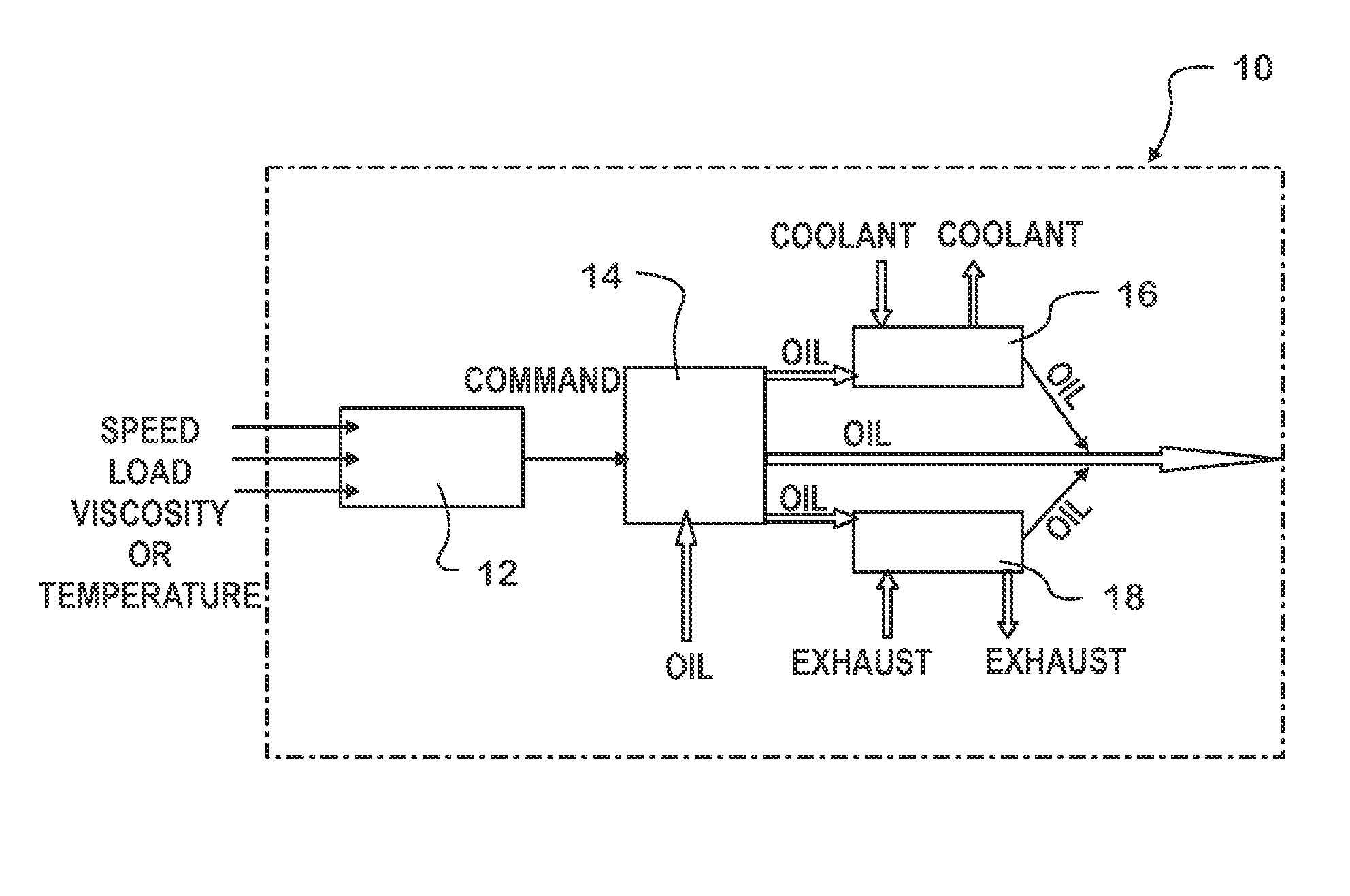
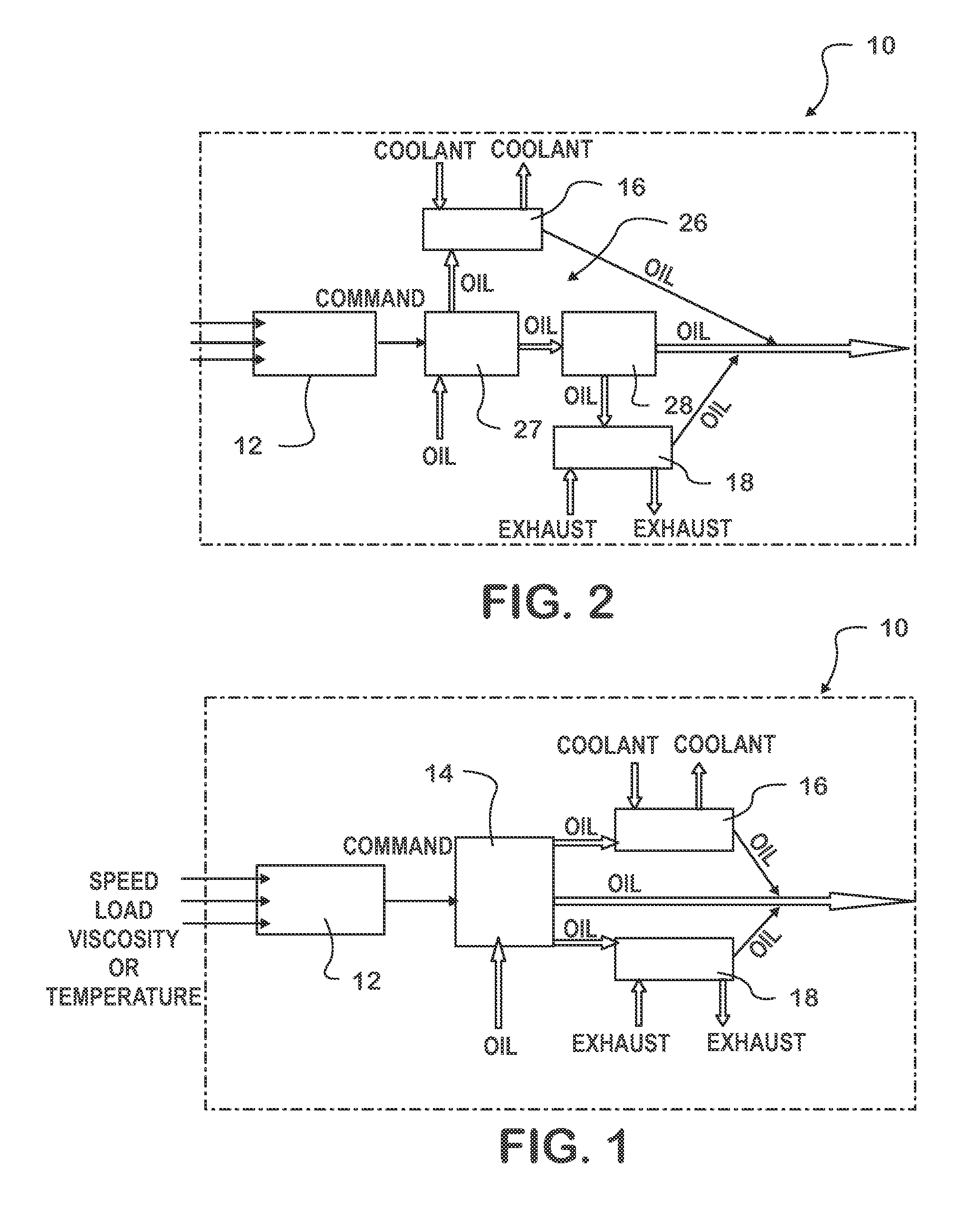
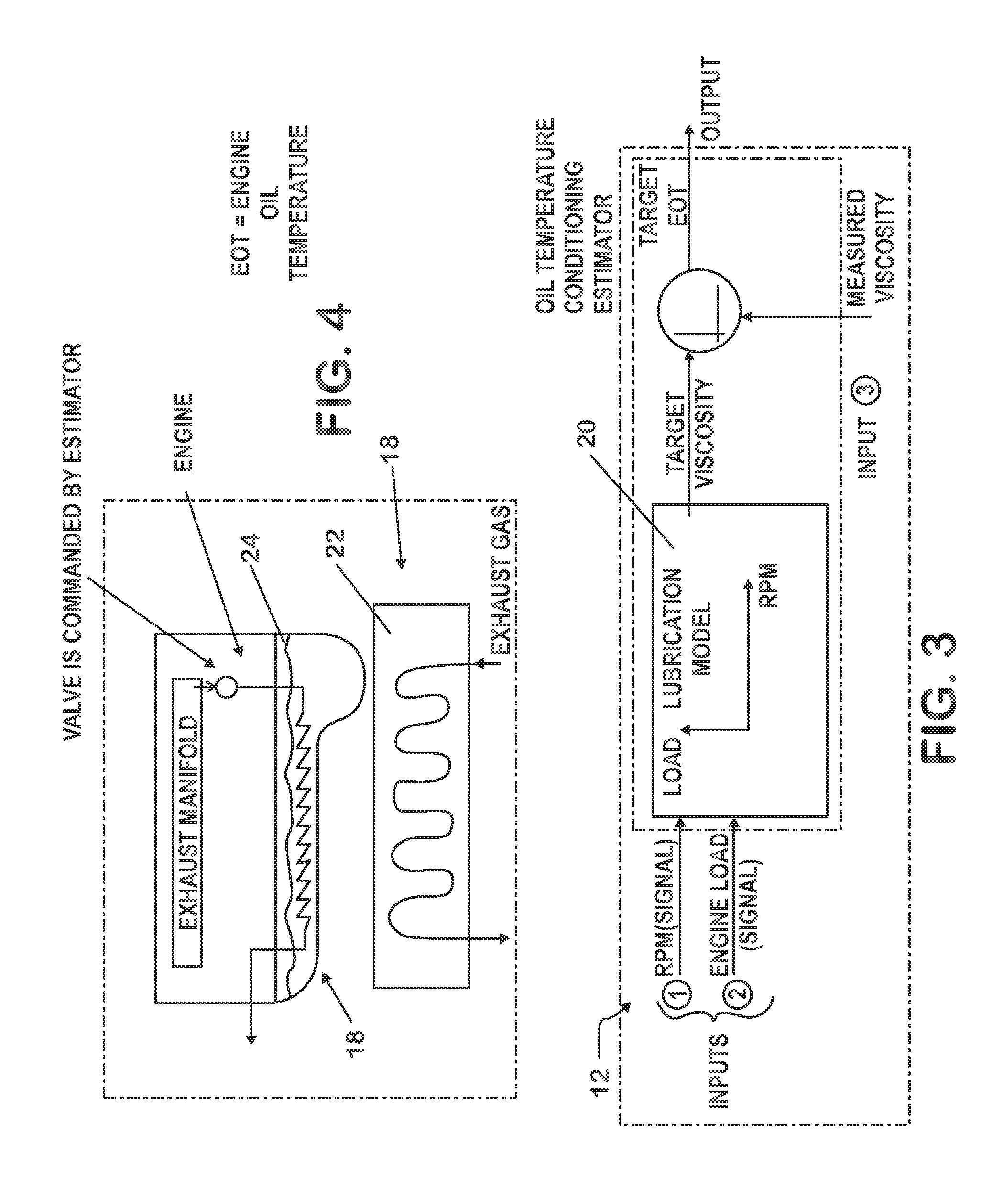
[0015]With reference to FIGS. 1-4, various embodiments of an engine oil management system are shown and consistently referenced by the number “10” throughout. Like components in the different embodiments are similarly referenced throughout the drawing figures and the following descriptions.

[0016]In a first illustrated embodiment of FIG. 1, the system 10 is generally comprised of an engine oil temperature conditioning estimator 12, a three-way valve 14, an engine oil cooler 16, and an engine oil heating mechanism 18.

[0017]The estimator 12 accepts engine speed and engine load signals from sensors (not shown) typically used in internal combustion engines to monitor engine operation conditions. The values of these signals are input to a lubrication model 20 within the estimator 12. The lubrication model 20 is generally a table which identifies a target engine oil viscosity based on parameters such as engine load and engine speed (RPMs). Once the signal values are input and a target oil ...


PUM


Abstract

A system and method for managing the characteristics of engine oil in a lubrication system for an internal combustion engine is disclosed. Generally speaking, the method includes the steps of determining a target viscosity for the engine oil based on engine speed and engine load, determining a working viscosity which may be directly measured or determined based on engine oil temperature and engine oil type, comparing the target viscosity to the working viscosity, deriving a target engine oil temperature, and directing engine oil to one of an oil cooler, an oil heater, or neither when and until the target engine oil temperature is achieved. The oil viscosity management system includes an engine lubrication system having a volume of engine oil, a cooler coupled to the lubrication system, a heating mechanism also coupled to the lubrication system, a valving system for directing flow of the oil and coupled to each of the lubrication system, the cooler and the heating mechanism, a signal generator for generating a signal based on operational parameters of the engine, and an estimator for controlling the valving system in response to the signal.

Description

TECHNICAL FIELD[0001]The present device and methods relate to engine oil management for an internal combustion engine. Specifically, the device relates to a system for accurately controlling the viscosity of engine oil based on operating parameters of the engine, while the methods relate to operation of the management system.BACKGROUND OF THE INVENTION[0002]The performance of an internal combustion engine is closely tied to fuel economy and operation temperature, which is in part a function of friction caused by the numerous moving parts of an engine. Engine oils have been engineered to provide adequate lubrication to such parts over a wide range of viscosities. However, optimizing viscosity to increase engine performance can be accomplished by controlling the engine oil temperature.[0003]Current systems use a thermostat to bypass an engine oil cooler when the oil temperature drops below a specified threshold. This allows the engine oil temperature to be raised until the threshold i...

Claims


Application Information

Patent Timeline
IPC IPC(8): F01M5/00
CPCF01M5/005F01N5/02Y02T10/12
Inventor CATTANI, LUIS CARLOSBEATTY, SCOTT A.CEYNOW, KENNETH P.AUGUST, JOSEPH WILLIAM
Owner INT ENGINE INTPROP CO LLC
Learn More