Hydrostatic Axial Piston Machine Employing A Bent-Axis Construction

a technology of axial piston machine and axial piston, which is applied in the direction of mechanical equipment, pumps, engines with rotating cylinders, etc., can solve the problems of critical stresses on the components of the axial piston machine, non-uniform torque on the drive shaft, and undesirable noise in the drive train

Inactive Publication Date: 2015-03-19
LINDE HYDRAULICS
View PDF4 Cites 0 Cited by
  • Summary
  • Abstract
  • Description
  • Claims
  • Application Information

AI Technical Summary

Benefits of technology

[0047]On the driving joint, which is in the form of a cone-beam semi-roller joint, which can be easily realized in the form of a constant velocity joint, for the drive of the cylinder drum, a variation of the pivoting angle, i.e., of the axes of rotation of the drive shaft and the cylinder drum with respect to each other, is also possible. The driving joint in the form of the cone-beam semi-roller joint is suitable for use ...

Problems solved by technology

In the event of a non-uniform rotation of the cylinder drum, the moment of inertia of the cylinder drum with the pistons located in it would cause a non-uniform torque on the drive shaft.
A non-uniform torque can result in critical stresses on the components of the axial piston machine.
Undesirable noises can also occur in a drive train of which the axial piston machine is a part on account of the non-uniform torque.
Although constant velocity joints of this type that utilize the Rzeppa principle or the tripod principle result in a rotationally synchronous drive of the cylinder drum, they are difficult and expensive to manufacture on account of the complex tracks for the balls or rollers.
In addition, at sufficiently high levels of torque to be transmitted to drive the cylinder drum, high Hertzian stresses occur on the roller bodies, which in constant velocity joints of this type are in the form of balls or rollers and require that the tracks be hardened to a significant depth.
During the necessary hardening by a suitable heat treatment of the components provided with the tracks for the roller bodies, a change in the dimensions of the hardened components that contain the tracks occurs, which requires complicated, expensive, and time-consuming mechanical reworking operations on the hardened components.
In other words, constant velocity joints that employ the Rzeppa or tripod principle require a high level of manufacturing effort and expense for the bent-axis machine.
In axial piston machines that utilize a bent-axis construction with drive of the cylinder drum by connecting rods or by pistons, however, on account of the limited number of pistons or connecting rods, it is not always possible to achieve an exactly rotationally synchronous drive of the cylinder drum and, thus, there is a non-uniformity of the rotational motion in the driving of the cylinder drum.
A further disadvantage of bent-axis axial piston machines with a cylinder drum driven by...

Method used


Image

  • Hydrostatic Axial Piston Machine Employing A Bent-Axis Construction
  • Hydrostatic Axial Piston Machine Employing A Bent-Axis Construction
  • Hydrostatic Axial Piston Machine Employing A Bent-Axis Construction

Examples


Embodiment Construction

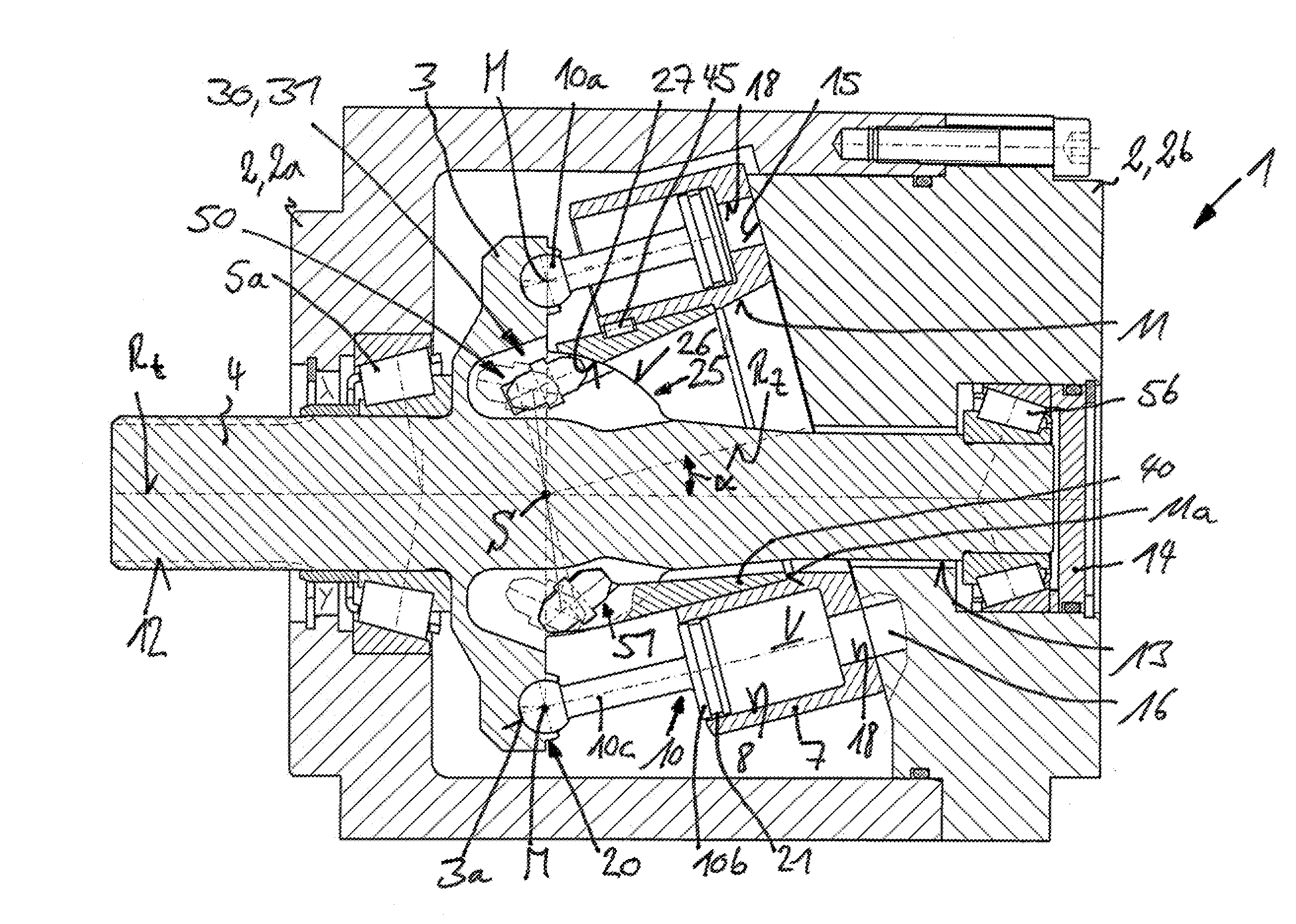
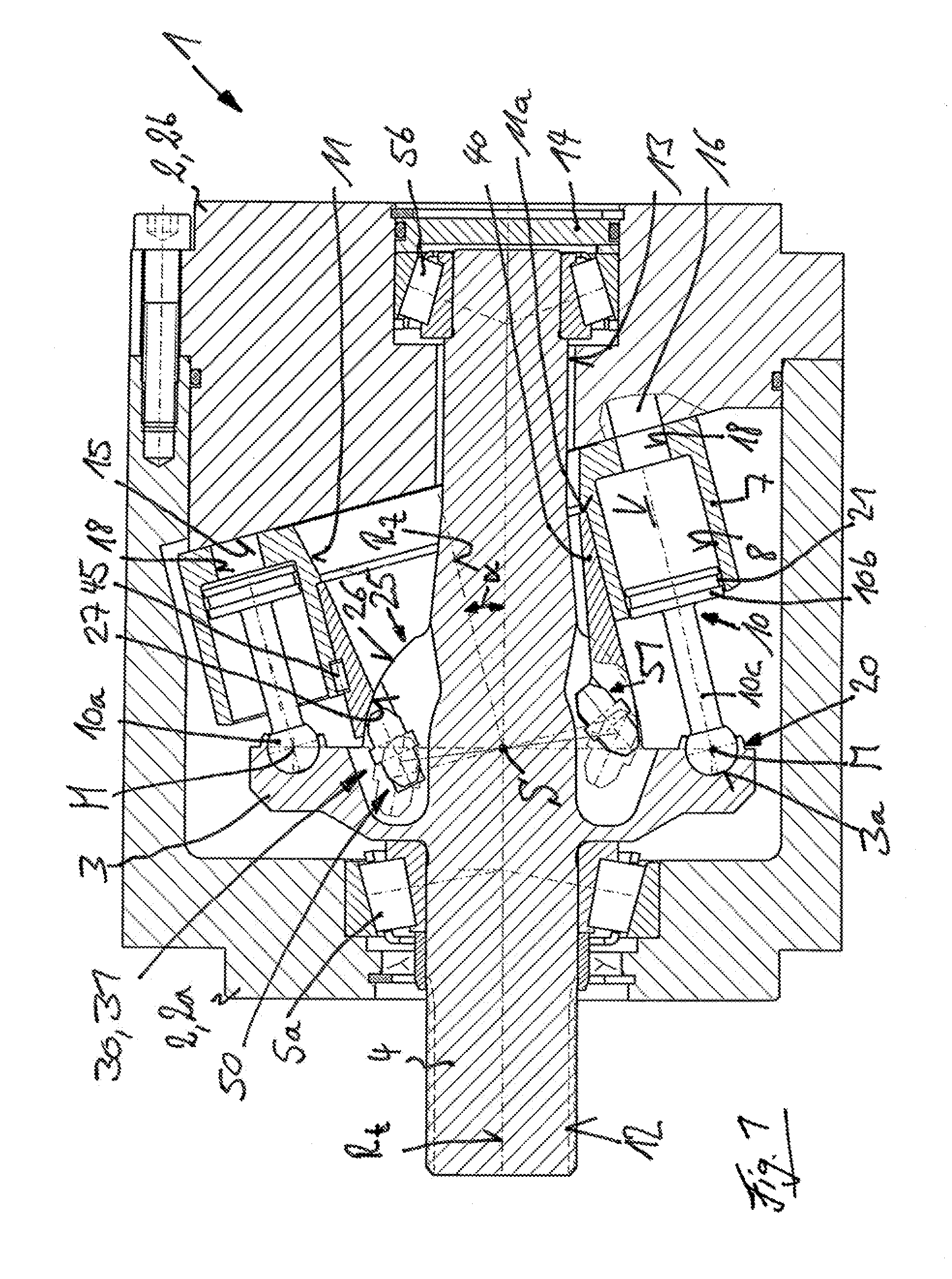
[0062]The hydrostatic axial piston machine 1 in the form of a bent-axis machine illustrated in FIG. 1 has a housing 2, which includes a housing pot 2a and a housing cover 2b. In the housing 2, a drive shaft 4 provided with the drive flange 3 is rotationally mounted by bearings 5a, 5b so that it can rotate around an axis of rotation R. In the illustrated exemplary embodiment, the drive flange 3 is formed in one piece with the drive shaft 4.

[0063]Located axially next to the drive flange 3 in the housing 2 is a cylinder drum 7 which is provided with a plurality of piston bores 8, which are arranged concentrically to an axis of rotation Rz of the cylinder drum 7. In each piston bore 8, there is a longitudinally displaceable piston 10.

[0064]The axis of rotation Rt of the drive shaft 4 intersects the axis of rotation Rz of the cylinder drum 7 at the intersection point S.

[0065]The cylinder drum 7 is provided with a central longitudinal bore 11 which is concentric with the axis of rotation ...


PUM


Abstract

A bent-axis hydrostatic axial piston machine (1) has a drive shaft (4) rotatable around an axis of rotation (Rt) and having a drive flange (3). A cylinder drum (7) is rotatable around an axis of rotation (Rz). The cylinder drum (7) includes a plurality of piston bores (8) concentric to the axis of rotation (Rz) of the cylinder drum (7) and in each of which piston bores (8) there is a longitudinally displaceable piston (10). The pistons (10) are fastened in an articulated manner to the drive flange (3). Between the drive shaft (4) and the cylinder drum (7) there is a constant velocity driving joint (30) in the form of a cone-beam semi-roller joint (31).

Description

CROSS REFERENCE TO RELATED APPLICATIONS[0001]This application claims priority to German Application No. DE 102013108406.0 filed Aug. 5, 2013, which is herein incorporated by reference in its entirety.BACKGROUND OF THE INVENTION[0002]1. Field of the Invention[0003]This invention relates to a hydrostatic axial piston machine employing a bent-axis construction with a drive shaft rotatable around an axis of rotation and having a drive flange. A cylinder drum is rotatable around an axis of rotation. The cylinder drum has a plurality of piston bores that are concentric to the axis of rotation of the cylinder drum. A longitudinally displaceable piston is located in each piston bore. The pistons are fastened in an articulated manner to the drive flange. Between the drive shaft and the cylinder drum there is a driving joint in the form of a constant velocity joint for rotationally synchronous rotation of the cylinder drum and the drive shaft.[0004]2. Description of Related Art[0005]In hydros...

Claims


Application Information

Patent Timeline
IPC IPC(8): F04B1/20F04B1/32
CPCF04B1/328F04B1/2092F01B3/0085F01B3/02F16J1/22F04B1/20F03C1/0607F03C1/0636F03C1/0673F03C1/0671F04B27/0865F04B27/086F04B1/2085F04B27/0869
Inventor BERGMANN, MARTIN
Owner LINDE HYDRAULICS
Why Eureka
Try Eureka