
Multiple gas sensor

a gas sensor and sensor technology, applied in the field of multiple gas sensors, can solve the problems of difficult to separate the contribution of each gas, difficult for a single sensor to accurately determine the relative contributions of carbon monoxide and hydrogen gases, and measurement of uncertainty

Inactive Publication Date: 2015-03-19
CROWCON DETECTION INSTR
View PDF1 Cites 27 Cited by
  • Summary
  • Abstract
  • Description
  • Claims
  • Application Information

AI Technical Summary

Benefits of technology

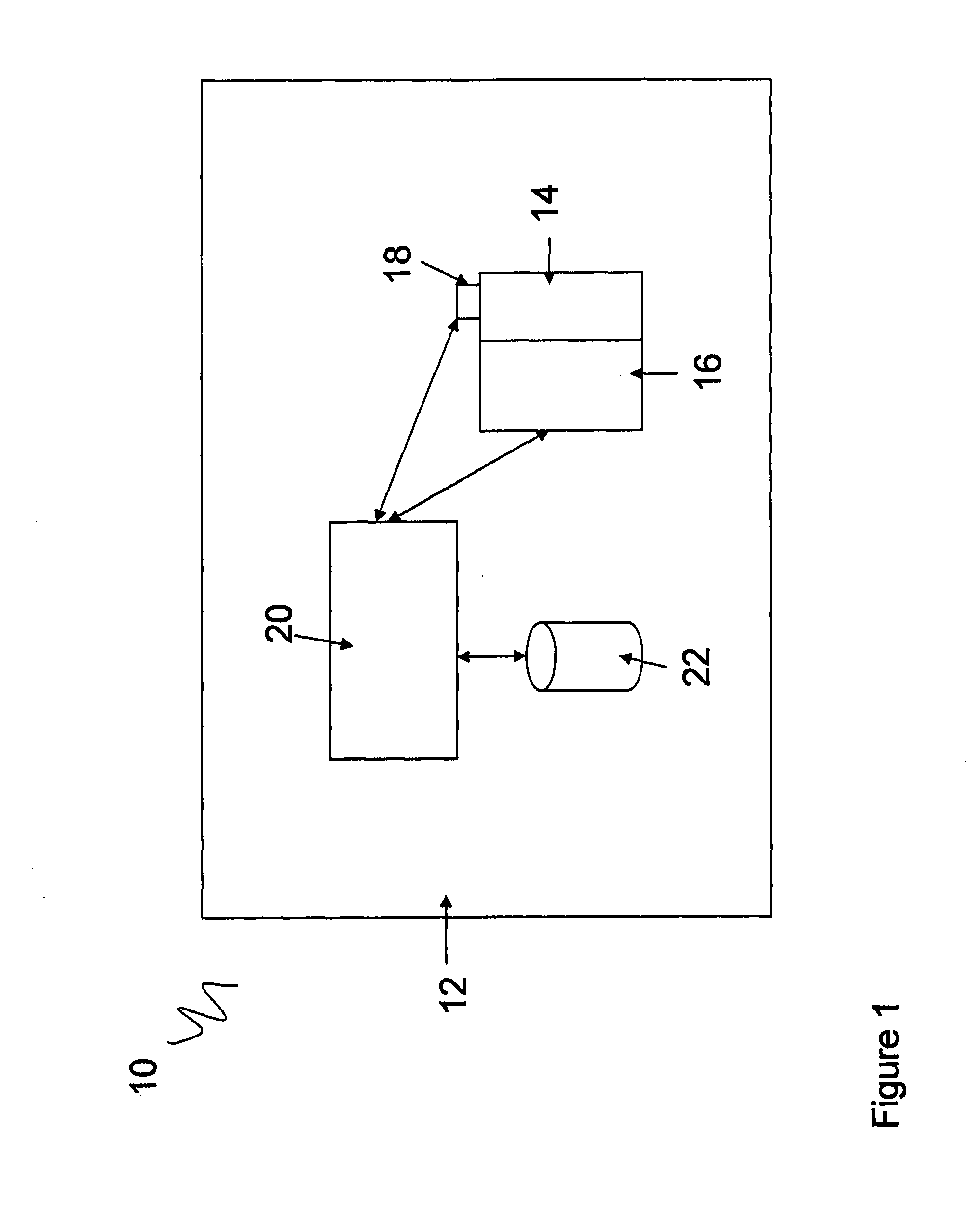
The present invention relates to a method and apparatus for determining the contributions of two or more target gases in an atmosphere. The invention addresses the problem of cross sensitivity in gas sensors, which can result in uncertainty when measuring the relative contributions of gases in a mixture. The invention provides a gas detector that can accurately determine the contributions of two or more target gases using a single gas sensor and compensates for cross sensitivity between different gases. This improves the selectivity and sensitivity of the gas sensor and reduces the risk of ignition or combustion in hazardous environments. The invention also includes a method of thermal control of the gas sensor to improve its selectivity and sensitivity to different gases.

Problems solved by technology

In such cases it may be difficult to separate the contribution from each gas in the total current response of the sensor.
In environments such as metal foundries where both types of gas could be present, it is difficult for a single sensor to accurately determine the relative contributions of the carbon monoxide and hydrogen gases due to the cross sensitivity of the sensors.
Accordingly, this results in a measure of uncertainty due to the mixture of the gases.
The requirements of individual sensors to determine the presence of a specific gas results in increased cost and associated maintenance costs.
Furthermore, the cross sensitivity of a sensor to two or more gases may result in less accurate readings returned by a gas detector.

Method used


Image

  • Multiple gas sensor
  • Multiple gas sensor
  • Multiple gas sensor

Examples


Embodiment Construction

[0015]There is described above a process of thermal control of a gas sensor which improves the selectivity and sensitivity of the sensor with respect to a plurality of gases. In particular, the present invention allows for the determination of a plurality of target gases with a single sensor, and also compensates for any cross sensitivity in a given sensor between two types of gases which would typically result in uncertainty in the measurements regarding the mixture of gases.

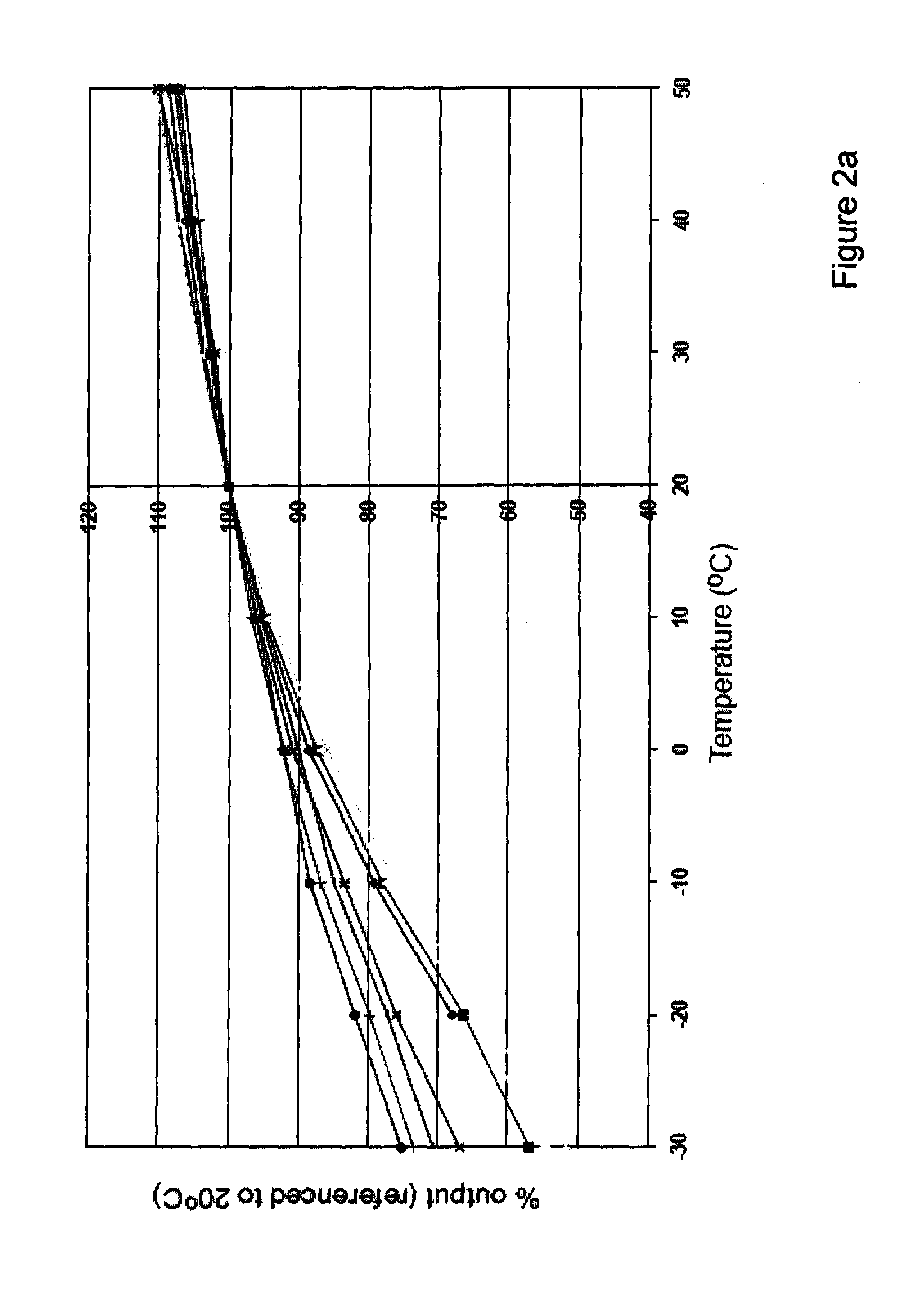
[0016]The response by a particular sensor to a particular gas may vary according to the temperature of the sensor. In particular it is found that sensors typically show much greater sensitivity to a given target gas at a particular temperature range (the temperature range being dependent on the gas being measured and the type of sensor). In the situation where a cross sensitivity may result from the presence of two or more gases in an atmosphere to be tested, for example Carbon Monoxide (CO) and Hydrogen (H2), ...


PUM


Abstract

A gas detector for determining the contributions of two or more target gases in an atmosphere to be sampled, the gas detector comprising: a gas sensor for sampling the gas, the gas sensor having a sensitivity to a target gas which is dependent on the temperature of the gas sensor; a temperature regulating device configured to change the temperature of the gas sensor; calculating means in communication with the gas sensor; wherein the gas detector is configured to: sample the atmosphere with the gas sensor at a plurality of temperatures, wherein the temperature regulating device changes the temperature of the sensor; and determine using the calculating means the contributions of the two or more target gases based on the measurements at the plurality of gas sensor temperatures and the sensitivity of the gas sensor at the plurality of gas sensor different temperatures.

Description

FIELD OF INVENTION[0001]The present invention relates to a method and apparatus to determine the contribution of two or more target gases in an atmosphere.BACKGROUND TO THE INVENTION[0002]It is known in commercially available systems to determine the level of a target gas or analyte using an electrochemical sensor (or equivalent). Such sensors are typically configured to determine with a reasonable level of accuracy the presence of an individual target gas. However in practice the sensors are typically placed in an environment which there may be several different gases, many of which will need to be monitored in order to ensure safety. For example, in a metal foundry, there may be found high concentrations of hydrogen and carbon monoxide, and the levels of both gases would need to be monitored on a regular basis in order to ensure safety.[0003]In modern instrumentation the output of a gas sensor is typically a current. Variations in the current output is indicative of the amount of ...

Claims


Application Information

Patent Timeline
IPC IPC(8): G01N33/00
CPCG01N33/0004G01N33/0016G01N33/0062G01N27/124G01N27/407G01N27/4162G01N33/0059
Inventor BASHAM, PAULHUTTON, ROGER
Owner CROWCON DETECTION INSTR
Learn More