
Spinal stabilization system

Inactive Publication Date: 2015-03-12
RINNER JAMES A
View PDF11 Cites 14 Cited by
  • Summary
  • Abstract
  • Description
  • Claims
  • Application Information

AI Technical Summary

Benefits of technology

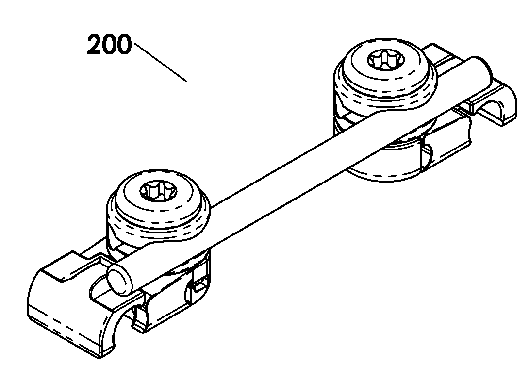
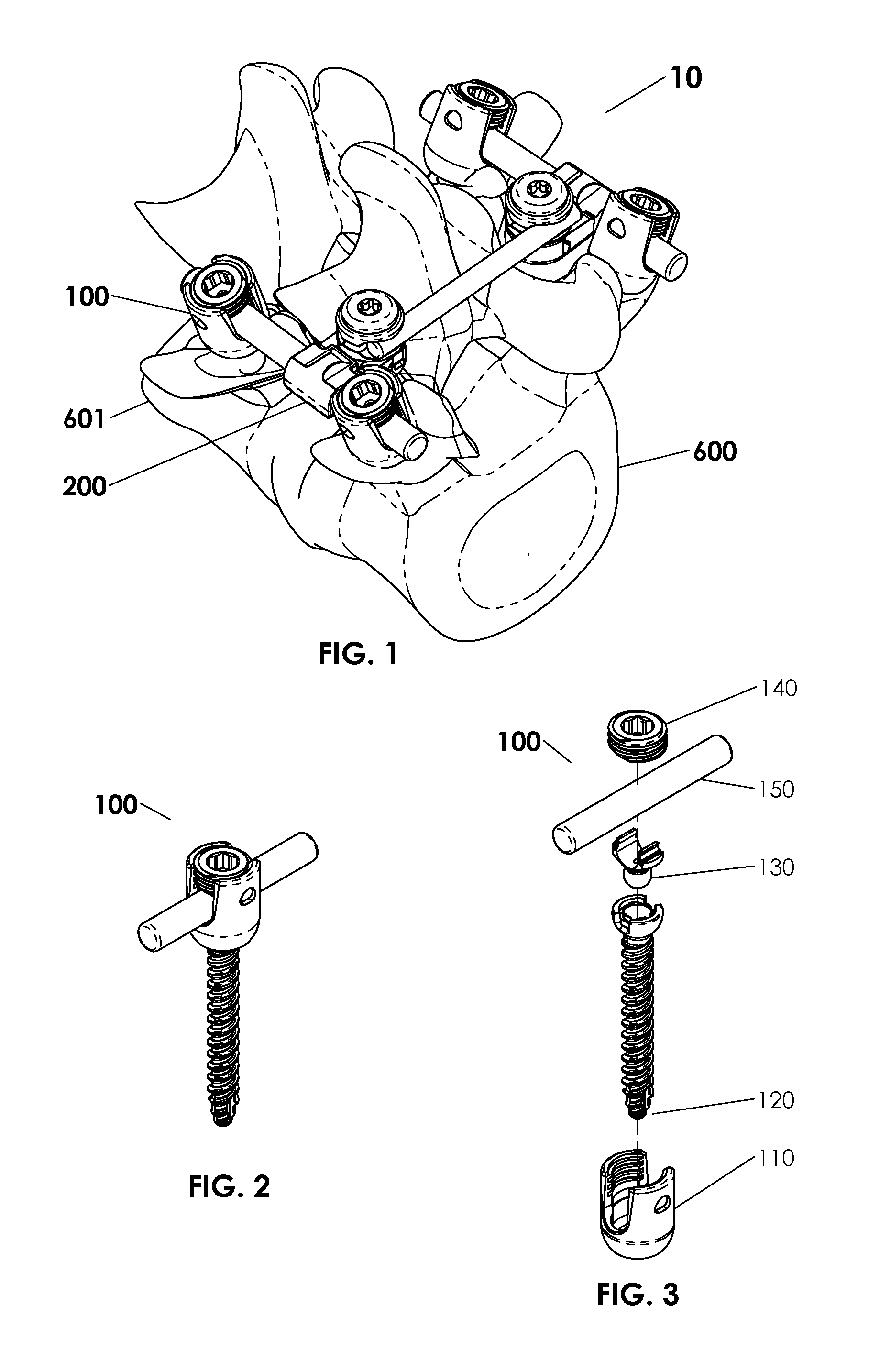
[0013]In another alternative embodiment, the spinal stabilization systems may comprise an angled polyaxial pedicle screw systems. Angled polyaxial pedicle screw systems may include a curved and/or bent support rod in conjunction with multiple tilted and/or angled tulip bodies, associated lower saddle inserts, and/or set screws. The bent support rod facilitates the placement of pedicle screw subassemblies in bony structures adjacent to each other, such as into pedicles of adjacent vertebral bodies, to ach

Problems solved by technology

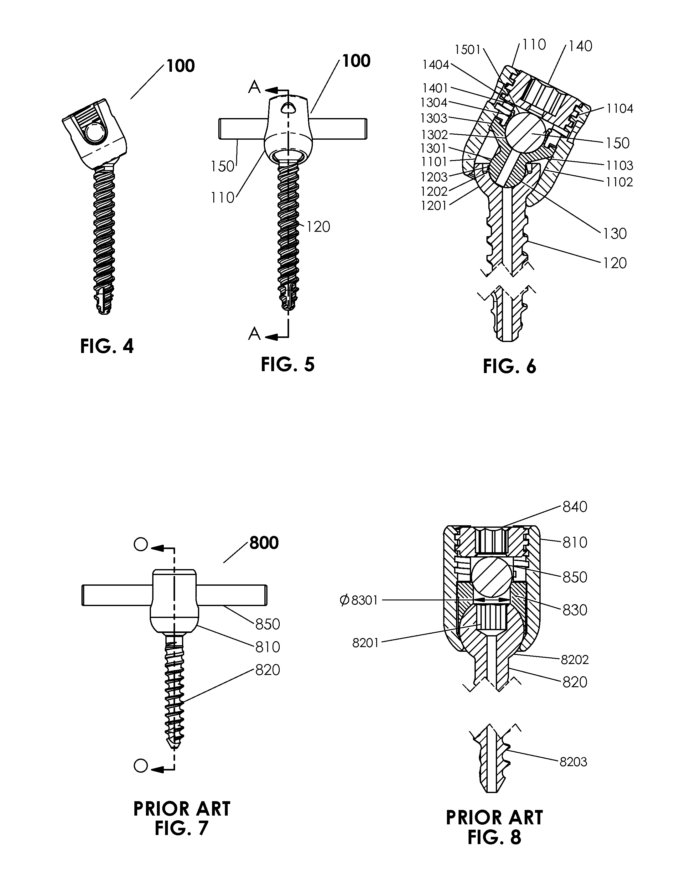
Unfortunately, existing pedicle screw systems are typically rather large and bulky, and the modularity and/or flexibility designed into the components in many of these systems can render the systems difficult for a surgeon to use effectively.
For example, the various feature that facilitate the assembly of different size and/or shape rod and screw constructs, and eventual “locking” of the components together (i.e., the pedicle screw assembly and the rod) to specified orientations, shapes and/or multi-axial angles (prior to fixation) can be difficult and/or impossible to assemble within a wound.
In many such instances, however, manufacturing and/or assembly of the tulip head, relevant inserts and/or the shank itself can result in a subassembly where the shank/head is loose and can “flop” around, making it extremely difficult for the surgeon to assemble the construct and/or tighten the remaining components together.
Alternatively, the tulip head may be too tight relative to the shank, rending it difficult and/or impossible for the surgeon to adjust the assembly by hand (prior to fixation).
Assembly difficulties can also be

Method used


Image

  • Spinal stabilization system
  • Spinal stabilization system
  • Spinal stabilization system

Examples


Example

DETAILED DESCRIPTION OF THE DRAWINGS

[0118]In the following detailed description, for purposes of explanation, numerous specific details are set forth to provide a thorough understanding of the various embodiments of the disclosure. Those of ordinary skill in the art will realize that these various embodiments are illustrative only and are not intended to be limiting in any way. In addition, for clarity purposes, not all of the routine features of the embodiments described herein may be shown or described for every alternative embodiment. One of ordinary skill in the art would readily appreciate that in the development of any such actual implementation, numerous implementation-specific decisions may be required to achieve specific design objectives. These design objectives may vary from one implementation to another and from one developer to another, and the variations thereof are contemplated and included in the present disclosure.

[0119]Various of the embodiments described herein in...


PUM


Abstract

The present invention is directed to a spinal implant system that incorporates unique snap, or spring loaded, features to assist the surgeon in the placement of screws, rods, hooks and transverse connectors. The poly-axial movement also uses a more direct loading lower saddle into the bone screw to improve locking of the construct.

Description

CROSS-REFERENCE TO OTHER APPLICATIONS[0001]This application is a continuation application of U.S. patent application Ser. No. 14 / 198,447 entitled “Spinal Stabilization System,” filed Mar. 5, 2014, and further claims the benefit of U.S. Provisional Patent Application Ser. No. 61 / 875,239 entitled “Spinal Stabilization System,” filed Sep. 9, 2013, the disclosures of which are both incorporated herein by reference in their entireties.TECHNICAL FIELD[0002]The present invention relates to devices and methods for assembling and adjusting orthopedic constructs connected to bony anatomy of a patient. More particularly, the present invention relates to improved devices and methods for pedicle screw and rod-based fixation assembly systems that utilize monoaxial and / or polyaxial bone screws, such as spinal fixation systems and associated components.BACKGROUND OF THE INVENTION[0003]A wide variety of surgical techniques and associated instrumentation systems have been developed for correcting deg...

Claims


Application Information

Patent Timeline
IPC IPC(8): A61B17/70
CPCA61B17/7052A61B17/7011A61B17/7032A61B17/7034A61B17/7035A61B17/7037A61B17/7046A61B17/7056A61B17/7076A61B17/8605A61B17/861
Inventor RINNER, JAMES A.
Owner RINNER JAMES A
Learn More