
Disparity Calculating Method and Stereo Matching Device thereof

a technology of disparity calculating and stereo matching, applied in image enhancement, image analysis, instruments, etc., can solve the problems of affecting the accuracy of depth information, errors in estimating disparities, and the display device may not generate multi-view images corresponding to the depth information to be projected on the human left and right eyes

Active Publication Date: 2015-03-05
NOVATEK MICROELECTRONICS CORP
View PDF5 Cites 10 Cited by
  • Summary
  • Abstract
  • Description
  • Claims
  • Application Information

AI Technical Summary

Benefits of technology

The patent text discusses the increasing diversity of display devices and the need for better outputting performance and resolution. One method for achieving this is through three-dimensional display functionality. The text describes different display methods that use special optical structures to project images with different views corresponding to depth information on human left and right eyes. This allows the human brain to capture the images with different views and results in a three-dimensional image. The technical effect of this patent is to provide a display device with improved performance and resolution using special optical structures for achieving three-dimensional display function.

Problems solved by technology

When two-dimensional images without the depth information are displayed by the display device having the three-dimensional display functionality, since the source images for displaying lack the depth information, the display device may not generate multi-views images corresponding to the depth information to be projected on the human left and right eyes.
However, when the stereo matching is performed between the two images with different views for obtaining the depth information, since landscapes of the two images are not entirely the same and the two images with different views may be captured by the two image capture devices with different distances from each other, searching for the matching objects between the two images with different views to obtain the accurate disparity information may affect accuracy of the depth information.
Due to occlusion effect, there are objects that cannot be matched in the images with two different views, resulting in errors when estimating the disparities.
For example, the pixels of the fringe area in an image (e.g. the left fringe and the right fringe of the image) do not have corresponding pixels in another image with another view, generally, resulting in that the disparity information of the fringe area in the image has greater errors and deviations.

Method used


Image

  • Disparity Calculating Method and Stereo Matching Device thereof
  • Disparity Calculating Method and Stereo Matching Device thereof
  • Disparity Calculating Method and Stereo Matching Device thereof

Examples


Embodiment Construction

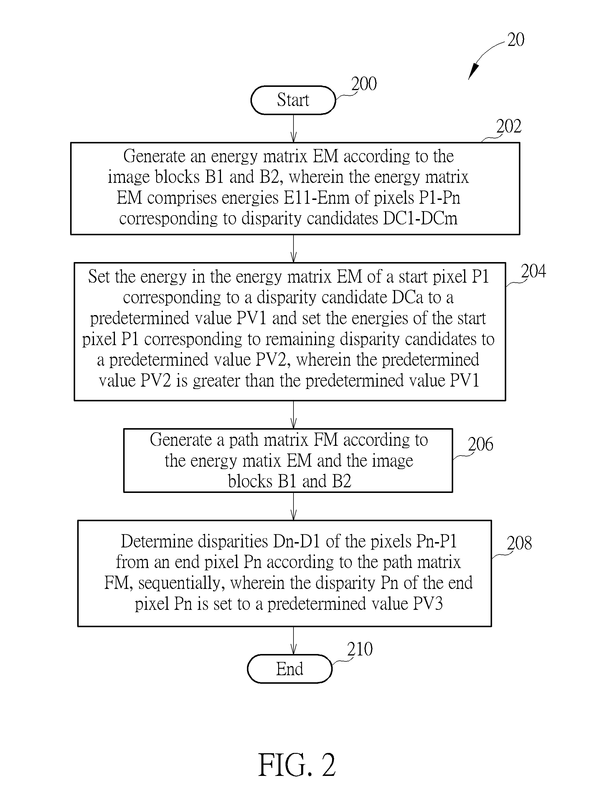
[0014]In embodiments of the present invention, a stereo matching device smoothes the disparity information of the fringe area via setting an energy of a start pixel in a scan line corresponding to a specific disparity candidate to a minimum value and setting a disparity of an end pixel of the scan line to a constant value when calculating the disparity information of two images with different views (e.g. images for left eye and right eye). The present invention is particularly shown and described with respect to at least one exemplary embodiment accompanied with drawings. Words utilized for describing connection between two components such as couple and connect should not be taken as limiting a connection between the two components to be directly coupling or indirectly coupling.

[0015]Please refer to FIG. 1, which is a schematic diagram of a stereo matching device 10 according to an example of the present invention. The stereo matching device 10 is utilized for calculating disparity ...


PUM


Abstract

A disparity calculating method includes generating an energy matrix according to a first image-block and a second image-block, wherein the energy matrix includes a plurality of energies of a plurality of pixels corresponding to a plurality of disparity candidates; setting the energy corresponding to a starting pixel of the plurality of pixels and a specified disparity candidate of the plurality of disparity candidates as a first predetermined value and setting the energies corresponding to the starting pixel and other disparity candidates of the plurality of disparity candidates as a second predetermined value, wherein the second predetermined value is greater than the first predetermined value; generating a path matrix according to the energy matrix; and determining a plurality of disparities of the plurality of pixels sequentially from an ending pixels of the plurality of pixels, wherein the disparity of the ending pixel is set as a third predetermined value.

Description

BACKGROUND OF THE INVENTION[0001]1. Field of the Invention[0002]The present invention relates to a disparity calculating method and stereo matching device thereof, and more particularly, to a disparity calculating method capable of smoothing the disparity information of the fringe area of the frame and stereo matching device thereof.[0003]2. Description of the Prior Art[0004]With continuously progressing image technologies, sizes and functionalities of display devices are increasingly diverse. In order to meet requirements of the different consumers, manufacturers of the display devices try to provide new products with better outputting performance and resolution. One of the most interesting products is a display device with three-dimensional display functionality. General three-dimensional display technologies include polarized, interlaced or anaglyph display methods. These display methods utilize special optical structures to project images with different views corresponding to de...

Claims


Application Information

Patent Timeline
IPC IPC(8): H04N13/00G06T5/00G06T7/00
CPCH04N13/0022H04N2013/0081G06T5/002G06T7/0075G06T2207/10012G06T7/593H04N13/128
Inventor LIU, GUANGZHIZHOU, LEICHOU, CHENG-WEI
Owner NOVATEK MICROELECTRONICS CORP
Learn More