
Carbon conductive substrate for electronic smoking article

a carbon conductive substrate and electronic smoking technology, applied in the direction of tobacco, lighting and heating apparatus, steam generation using steam absorption, etc., can solve the problems of delivering large quantities of incomplete combustion and pyrolysis products, and achieve the effect of slowing down the degradation of materials and improving the disposable nature of the cartridg

Active Publication Date: 2015-03-05
RAI STRATEGIC HLDG INC
View PDF4 Cites 588 Cited by
  • Summary
  • Abstract
  • Description
  • Claims
  • Application Information

AI Technical Summary

Benefits of technology

The present invention is about the materials used in electronic smoking devices to create the aerosol. The invention suggests using carbon materials as the main ingredient in the cartridge, which makes the device more disposable and avoids the use of slow-degrading materials. This results in a better user experience and improved functionality of the device.

Problems solved by technology

Many of those devices purportedly have been designed to provide the sensations associated with cigarette, cigar, or pipe smoking, but without delivering considerable quantities of incomplete combustion and pyrolysis products that result from the burning of tobacco.

Method used


Image

  • Carbon conductive substrate for electronic smoking article
  • Carbon conductive substrate for electronic smoking article
  • Carbon conductive substrate for electronic smoking article

Examples


example 1

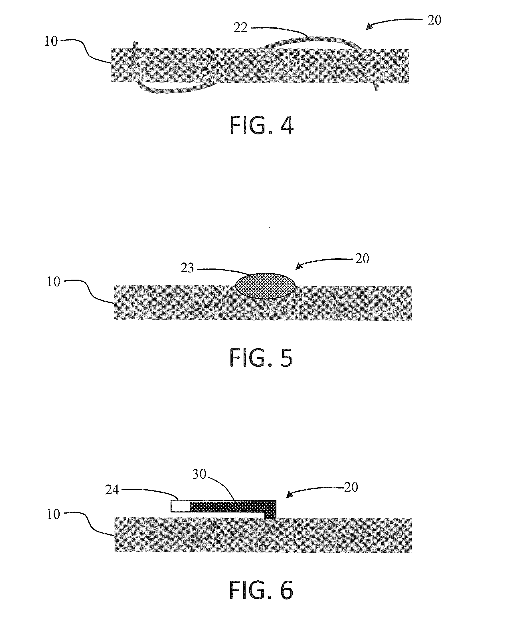
[0129]A cylindrical rod 3 mm in diameter and 10 mm in length was made from 0.17 g / cm3 carbon foam. Three equally spaced holes about 1 mm in diameter were drilled in the carbon. The holes went through the entire width of the foam. A cotton fiber was threaded through the holes as shown in FIG. 4. An aerosol precursor solution was applied to the fiber-foam assembly. The fiber served as a reservoir for the precursor solution. A current of 4.2 volts and 0.9 amps was passed through the substrate. More than 30 puffs of aerosol were generated.

example 2

[0130]A cylindrical rod of 3 mm in diameter and 10 mm in length was made from 0.17 g / cc carbon foam. A hole of about 1.5 mm in diameter and 1.5 mm in depth was drilled at the center of the carbon foam. A cotton ball saturated with an aerosol precursor solution was inserted in the hole as shown FIG. 5. A current of 4.2 volts and 0.9 amps was passed through the substrate. More than 30 puffs of aerosol were generated.

example 3

[0131]A cylindrical rod 3 mm in diameter and 10 mm in length was made from 0.17 g / cm3 carbon foam. The rod was inserted in the center of a disk formed of carbon fabric having a thickness of about 2 mm and a diameter of about 4 mm. About 0.6 mL of an aerosol precursor solution as applied to the assembly. A current of 4.2 volts and 0.7 amps was applied to the carbon foam heater, and more than 120 puffs of aerosol were generated. An illustration of the exemplary atomizer assembly 2000 formed of the carbon foam heater 2010 and the carbon fabric aerosol precursor transport element 2100 is shown in FIG. 22. Additional exemplary atomizer assemblies are shown in FIG. 23 through FIG. 25. In FIG. 23, the carbon fabric aerosol precursor transport element 2100 is arranged aside the porous carbon heater 2010 along the length thereof. In FIG. 24, two carbon fabric aerosol precursor transport elements 2100a and 2100b is arranged aside two sides of the porous carbon heater 2010 along the length the...


PUM

PropertyMeasurementUnit
temperatureaaaaaaaaaa
densityaaaaaaaaaa
densityaaaaaaaaaa

Abstract

The present disclosure provides components useful in heating, particularly heating of an aerosol precursor solution so as to vaporize the solution and form an aerosol. The disclosure particularly provides an electrically conductive, porous carbon heater. The heater may be combined with an aerosol precursor transport element that also is formed of carbon. The heater and transport element may form an atomizer that can be useful in an electronic smoking article, such as in a cartridge that is adapted for attachment to a control body. In some embodiments, the disclosure provides a cartridge of an electronic smoking article, the cartridge being formed substantially completely of carbon.

Description

FIELD OF THE DISCLOSURE[0001]The present disclosure relates to aerosol delivery devices such as smoking articles, and more particularly to electrically resistive heaters useful in such devices. The electrically resistive heaters may be configured to heat a material, which may be made or derived from tobacco or otherwise incorporate tobacco, to form an inhalable substance for human consumption.BACKGROUND[0002]Many smoking devices have been proposed through the years as improvements upon, or alternatives to, smoking products that require combusting tobacco for use. Many of those devices purportedly have been designed to provide the sensations associated with cigarette, cigar, or pipe smoking, but without delivering considerable quantities of incomplete combustion and pyrolysis products that result from the burning of tobacco. To this end, there have been proposed numerous smoking products, flavor generators, and medicinal inhalers that utilize electrical energy to vaporize or heat a v...

Claims


Application Information

Patent Timeline
Patent Type & Authority Applications(United States)
IPC IPC(8): A24F47/00A24F40/10A24F40/44A24F40/46
CPCA24F47/008A24F40/46A24F40/10A24F40/44A24F40/42
Inventor DAVIS, MICHAEL F.ADEME, BALAGERBANERJEE, CHANDRA KUMARPIKE, SUSAN K.GRIFFITH, JR., DAVID WILLIAMSEARS, STEPHEN BENSONCROOKS, EVON L.WILLIAMS, KAREN V.NESTOR, TIMOTHY BRIANBOVENDER, DAVID
Owner RAI STRATEGIC HLDG INC
Learn More