
Electric power steering system

a technology of steering system and electric motor, which is applied in the direction of steering initiation, instruments, vessel construction, etc., can solve the problems of deterioration of the steering feel of the driver, and achieve the effect of improving the steering feel

Active Publication Date: 2015-02-26
JTEKT CORP
View PDF3 Cites 9 Cited by
  • Summary
  • Abstract
  • Description
  • Claims
  • Application Information

AI Technical Summary

Benefits of technology

The invention is an electric power steering system that improves the feel of steering when the wheel is near the neutral position. It uses a feedback control system to adjust the assist force based on the steered angle, so that the actual steering angle matches the command value. This helps to cancel out friction and make the steering feel more natural. The system also adjusts a correction component to decrease the assist force, giving the driver a more tactile response when the wheel is near the neutral position. Overall, this system creates a better steering experience for drivers.

Problems solved by technology

This may be a factor of deterioration of the driver's steering feel.

Method used


Image

  • Electric power steering system
  • Electric power steering system
  • Electric power steering system

Examples


first embodiment

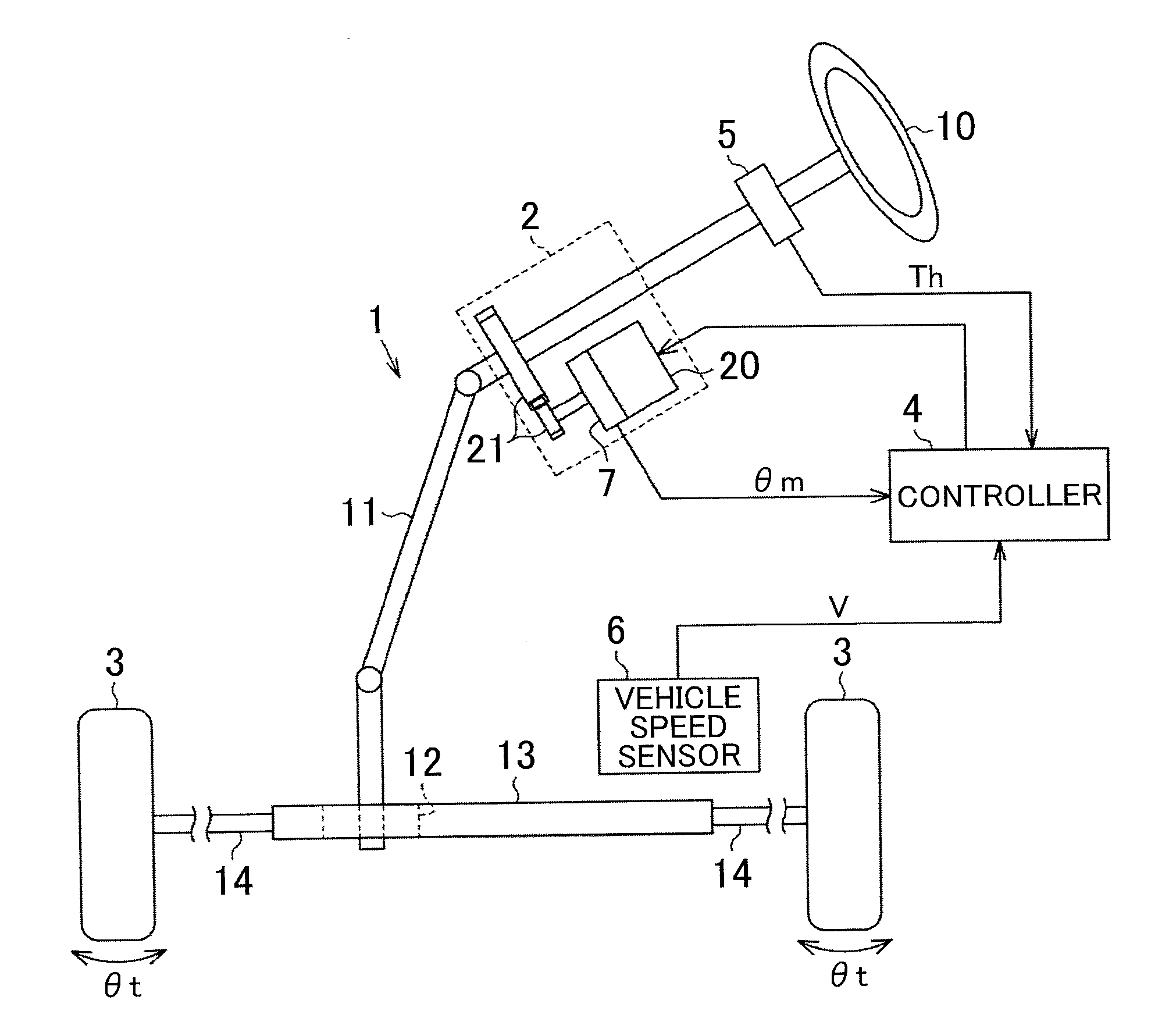
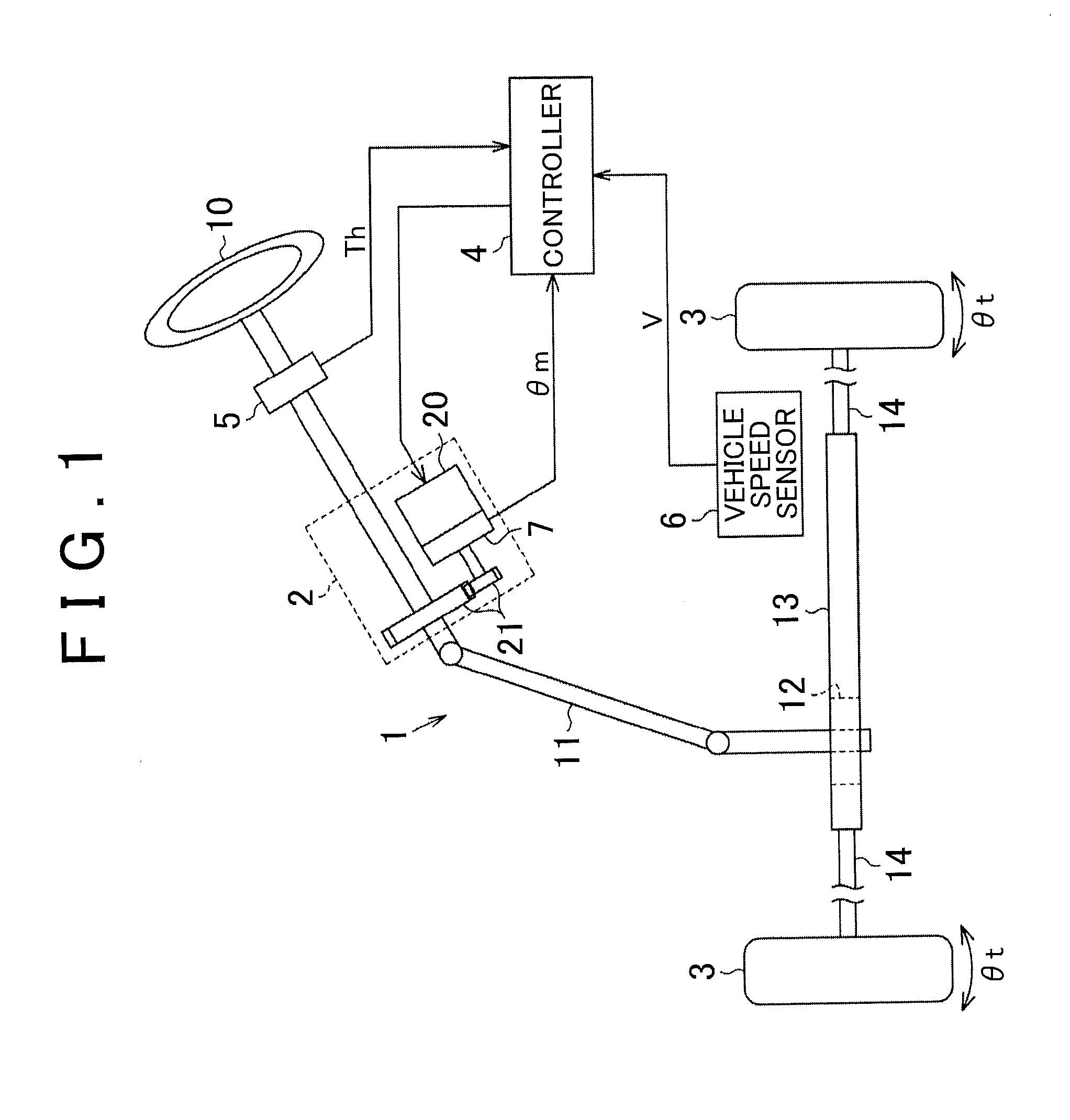
[0036]Hereinafter, an electric power steering system according to the invention will be described. First, the outline of the electric power steering system will be described.

[0037]As illustrated in FIG. 1, the electric power steering system includes a steering mechanism 1 that steers steered wheels 3 in response to a driver's operation of a steering wheel 10, and an assist mechanism 2 that assists a driver's steering operation.

[0038]The steering mechanism 1 includes a steering shaft 11 that serves as a rotary shaft of the steering wheel 10, and a rack shaft 13 that is connected to a lower end portion of the steering shaft 11 via a rack-and-pinion mechanism 12. In the steering mechanism 1, when the steering shaft 11 is rotated in response to a driver's operation of the steering wheel 10, the rotary motion is converted into a linear reciprocating motion of the rack shaft 23 in its axial direction via the rack-and-pinion mechanism 12. The linear reciprocating motion of the rack shaft 1...

second embodiment

[0106]Next, a first modified example of the second embodiment will be described. In this modified example, the vehicle state determination unit 111 further determines the vehicle state based on the vehicle speed V detected by the vehicle speed sensor 6. Specifically, as illustrated in FIG. 23, when it is determined that the steering wheel 10 is positioned near the neutral position (S3: YES), the vehicle state determination unit 111 determines whether the vehicle speed V is lower than or equal to a prescribed speed threshold Va (S5). The speed threshold Va is set, in advance through, for example, an experiment, to such a value that whether the vehicle is travelling at a low speed can be determined, and is then stored in a memory. When the vehicle speed V exceeds the prescribed speed threshold Va (S5: NO), the vehicle state determination unit 111 outputs the adjustment signal Sa (S4). When the vehicle speed V is lower than or equal to the prescribed speed threshold Va (S5: YES), the v...


PUM


Abstract

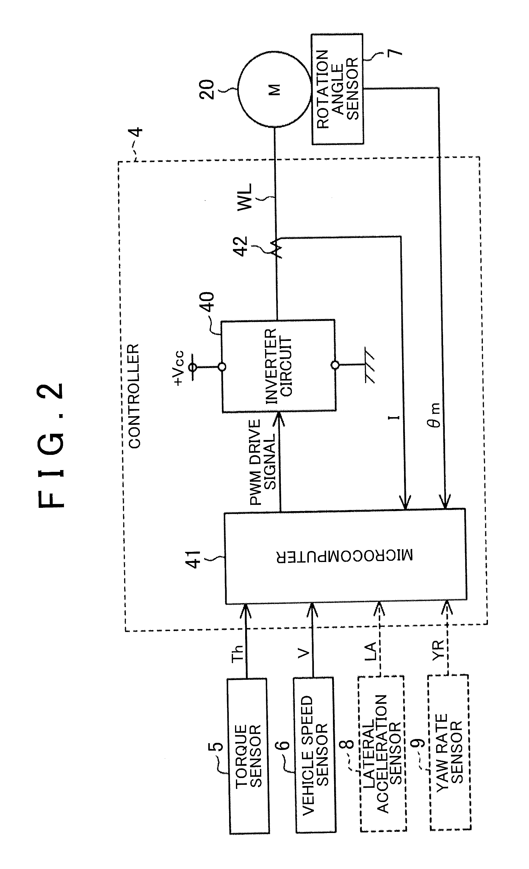
A controller of an electric power steering system includes: a basic assist component computing unit (60) that computes a first assist component (Ta1*) based on a steering torque (Th); a steered angle command value computing unit (61) that computes a steered angle command value (θt*) based on the sum of the steering torque (Th) and the first assist component (Ta1*); and a steered angle feedback controller (62) that computes a second assist component (Ta2*) through feedback control on an actual steered angle (θt). The controller further includes: a correction component computing unit (65) that computes a correction component (Tc*) based on a steering angle (θs); and an assist command value computing unit (50) that computes an assist command value (Ta*) by subtracting the correction component (Tc*) from the sum of the first assist component (Ta1*) and the second assist component (Ta2*).

Description

INCORPORATION BY REFERENCE[0001]The disclosures of Japanese Patent Applications No. 2013-174700 and No. 2014-θ26804 respectively filed on Aug. 26, 2013 and Feb. 14, 2014, each including the specification, drawings and abstract, are incorporated herein by reference in their entireties.BACKGROUND OF THE INVENTION[0002]1. Field of the Invention[0003]The invention relates to an electric power steering system that assists a vehicle steering operation.[0004]2. Description of the Related Art[0005]Japanese Patent Application Publication No. 2011-46293 (JP 2011-46293 A) describes an electric power steering system that includes a steering mechanism that steers steered wheels of a vehicle in response to an operation of a steering wheel, and an assist mechanism that applies assist force to the steering mechanism. The assist mechanism is provided with various sensors that detect, for example, a steering torque applied to the steering wheel and a vehicle speed, and a controller that controls driv...

Claims


Application Information

Patent Timeline
IPC IPC(8): B62D5/04B62D6/10
CPCB62D6/10B62D5/0463B62D5/046B62D6/00B62D6/008
Inventor TAMAIZUMI, TERUTAKAKITA, MASAYUKINAMIKAWA, ISAOEKI, HIROZUMI
Owner JTEKT CORP
Learn More