Secondary coil of receiver for non-contact charging system

Inactive Publication Date: 2015-02-26
KIM SEON SEOB
View PDF2 Cites 36 Cited by
  • Summary
  • Abstract
  • Description
  • Claims
  • Application Information

AI Technical Summary

Benefits of technology

[0034]According to the present invention, with regard to a non-contact charging system for charging a battery using electromagnetic induction generated between a primary coil of a transmitter and a secondary coil of a receiver, as coils having a non-ove

Problems solved by technology

However, the “charging cover”-based charging method is inconvenient in that “the charging cover” should be separately provided for non-contact charging of the cellular phone.
Furthermore, as the area of the vertically overlapping portion of the two coils reduces gradually, the induced electromotive force also reduces, and thus charging efficiency reduces gradually.
However, “the motor control method” and “the multiple primary coil-based method” are disadvantageous in that a product cost is relatively increased compared to “the magnetic method” due to an increase in the number of parts.
Also, the motor control method has a limit in that a weight of the primary coil should be limited in order to reduce a load applied to the motor, and the multiple primary coil-based method is problematic in that a

Method used


Image

  • Secondary coil of receiver for non-contact charging system
  • Secondary coil of receiver for non-contact charging system
  • Secondary coil of receiver for non-contact charging system

Examples


Example

BEST MODE

[0042]Hereinafter, the present invention will be described in detail with reference to the accompanying drawings. The detailed examples disclosed herein is for the purpose of exemplarily describing the present invention only and is not intended to limit a scope of the present invention.

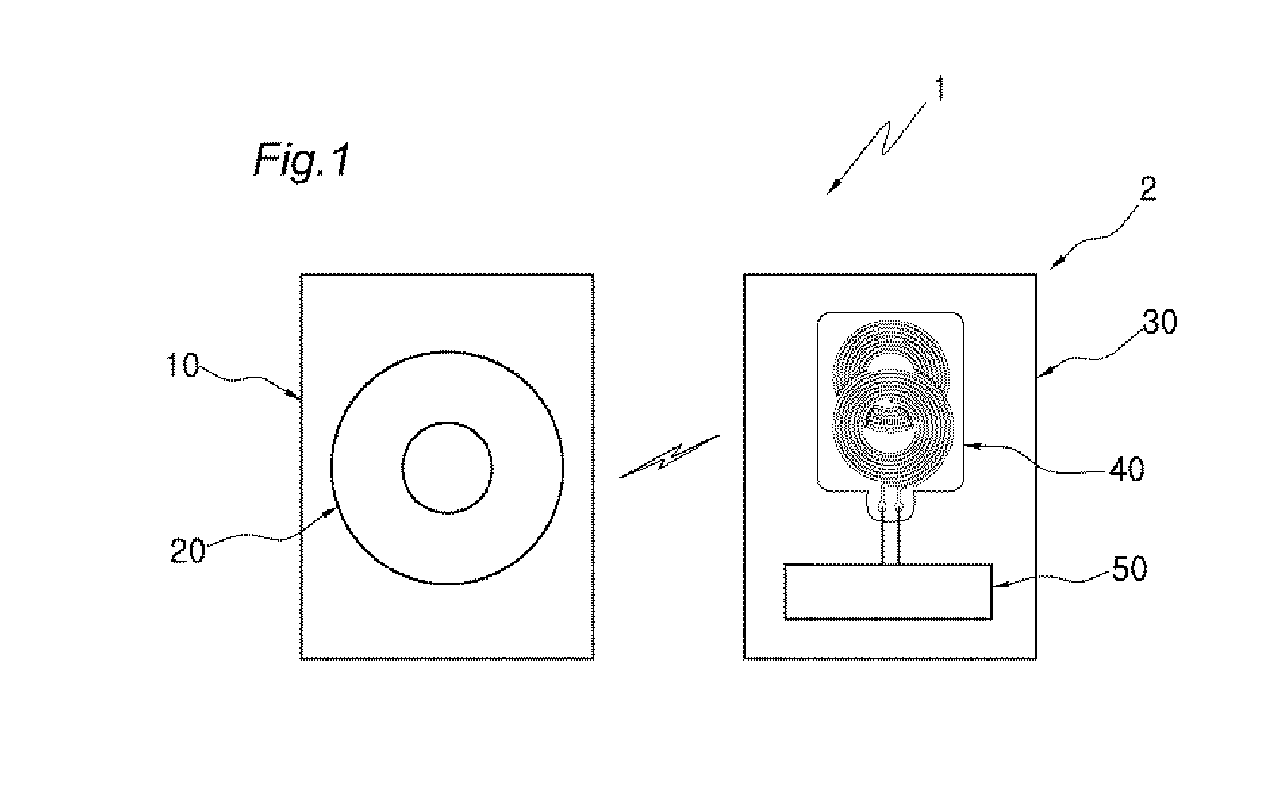
[0043]As illustrated in FIG. 1, like a conventional non-contact charging system applied to a cellular phone which is a representative portable device 2, a non-contact charging system 1 to which a secondary coil 40 of the present invention is applied includes: a transmitter 10 (e.g., a charging mat) in which a primary coil 20 is installed; and a receiver 30 (e.g., a cellular phone) in which the secondary coil 40 is installed. Hereinafter, a cellular phone will be mainly described as an example of the portable device 2, and the portable device and the cellular phone will refer to the same reference numeral 2 of the drawing.

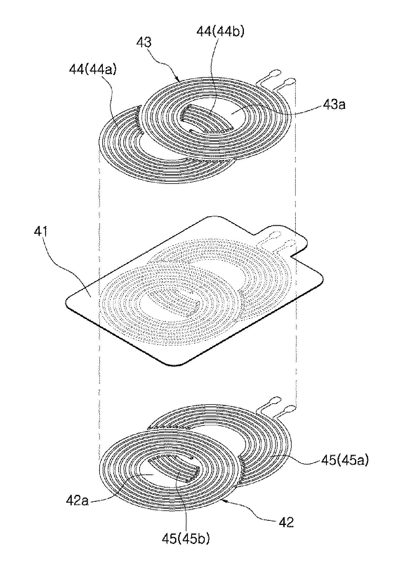
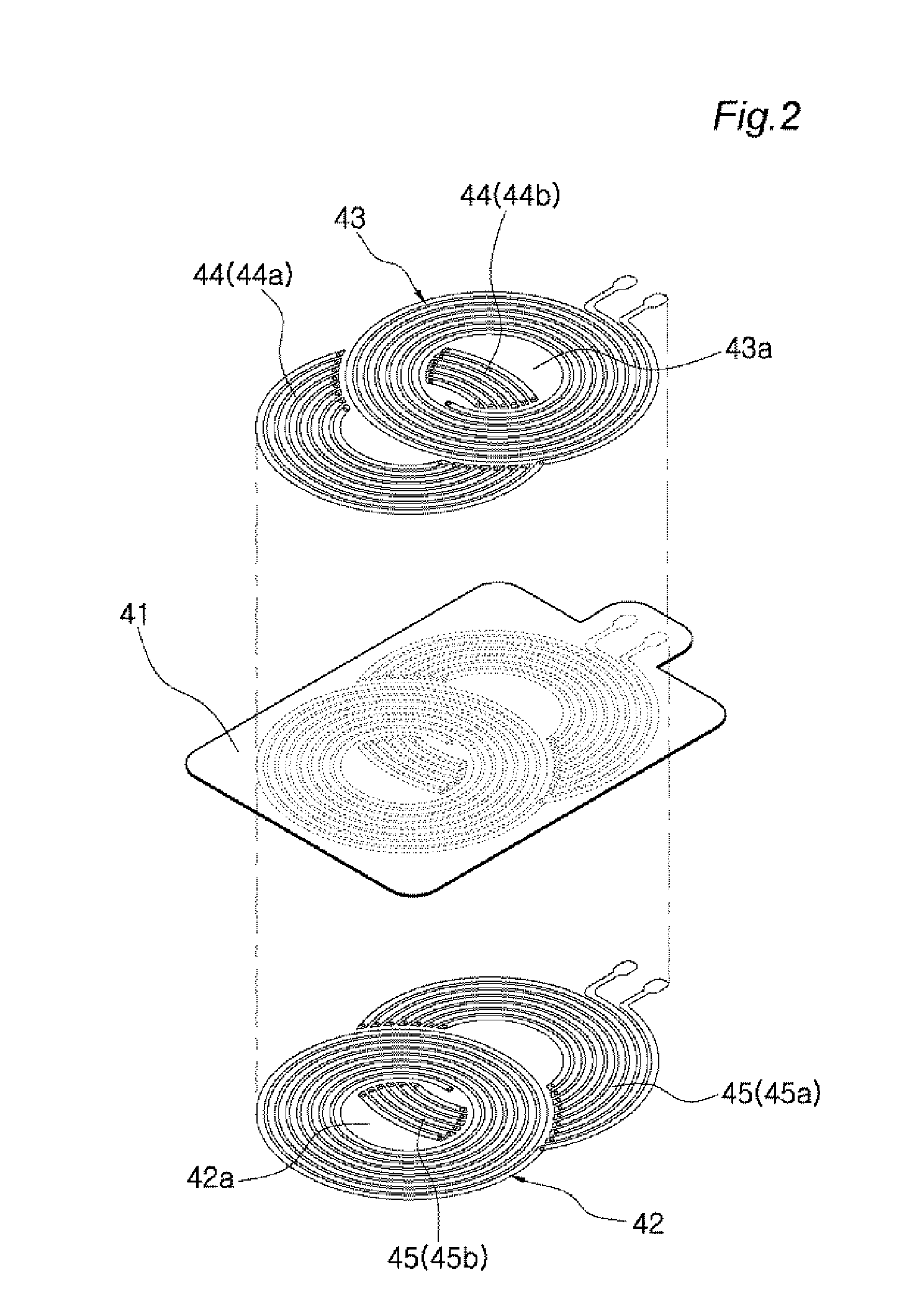
[0044]As known, in addition to the primary coil 20 and the secondary coi...


PUM


Abstract

Provided is a secondary coil (40) applied to an electromagnetic induction type non-contact charging system according to the present invention, the secondary coil including: a substrate (41); a first coil 42 stacked on one side of the substrate (41) and having a first internal space (42a) formed in its center; a second coil 43 stacked on the other side of the substrate (41) and having a second internal space (43a) formed in its center; a first additional pattern (44) electrically connected to the first coil (42); and a second additional pattern (45) electrically connected to the second coil (43), wherein the first internal space (42a) and the second internal space (43a) are not vertically aligned, but “are non-overlappingly arranged” to deviate by a predetermined distance in a horizontal direction.

Description

TECHNICAL FIELD[0001]The present invention relates, in general, to a non-contact charging system and, more particularly, to a secondary coil of a receiver for a non-contact charging system for charging a battery electrically connected to the secondary coil using electromagnetic induction generated between a primary coil of a transmitter and the secondary coil of the receiver, placed close to the primary coil.BACKGROUND ART[0002]A multi rechargeable battery has been widely used instead of a disposable battery to supply power to various portable devices as well as cellular phones. Typically, a wire (contact) charging method was widely used in the charging of the rechargeable battery, but the use of a non-contact (wireless) charging method has been recently increasing.[0003]Examples of conventional arts regarding non-contact charging of cellular phones are the following: ‘Contactless charging system of radio telephone’ disclosed in Korean Patent Publication No. 10-1995-0005819 (publish...

Claims


Application Information

Patent Timeline
IPC IPC(8): H01F27/28H02J7/02
CPCH02J7/025H01F27/2823H02J5/005H01F27/28H01F38/14H04B5/0075H04B5/0037H01F27/2804H02J50/10H02J50/005H02J7/00714H02J50/90
Inventor KIM, SEON SEOB
Owner KIM SEON SEOB
Why Eureka
Try Eureka