
System and method for providing resilience in communicaton networks

a technology of communication network and resilience, applied in the field of optical network, can solve the problems of no media other than optical fibre cable (ofc) has been successfully used to increase the resiliency of optical network, no resiliency at all, and no reliabl

Active Publication Date: 2015-02-05
STERLITE NETWORKS LIMTED
View PDF4 Cites 2 Cited by
  • Summary
  • Abstract
  • Description
  • Claims
  • Application Information

AI Technical Summary

Benefits of technology

The present invention aims to enhance the resilience of optical networks, specifically PON networks. The objective is to provide solutions that meet customer expectations for faster and efficient services.

Problems solved by technology

More specifically, it has been noted that over the years, no media other than the Optical Fibre Cable (OFC) has been successfully used for increasing the resiliency of optical networks.
However, such technique is not very reliable since the backup optical fiber cables may also break down thereby resulting in no resiliency at all.
Also, at times it is difficult to lay optical fiber cables and thus it is difficult to ensure network resiliency.

Method used


Image

  • System and method for providing resilience in communicaton networks
  • System and method for providing resilience in communicaton networks
  • System and method for providing resilience in communicaton networks

Examples


Embodiment Construction

[0023]For a thorough understanding of the present disclosure, reference is to be made to the following detailed description, including the appended claims. Although the present disclosure is described in connection with exemplary embodiments, the present invention is not intended to be limited to the specific forms set forth herein. It is understood that various omissions and substitutions of equivalents are contemplated as circumstances may suggest or render expedient, but these are intended to cover the application or implementation without departing from the spirit or scope of the claims of the present invention. Also, it is to be understood that the phraseology and terminology used herein is for the purpose of description and should not be regarded as limiting.

[0024]The terms “a” and “an” herein do not denote a limitation of quantity, but rather denote the presence of at least one of the referenced item.

[0025]The terms “having”, “comprising”, “including”, and variations thereof ...


PUM


Abstract

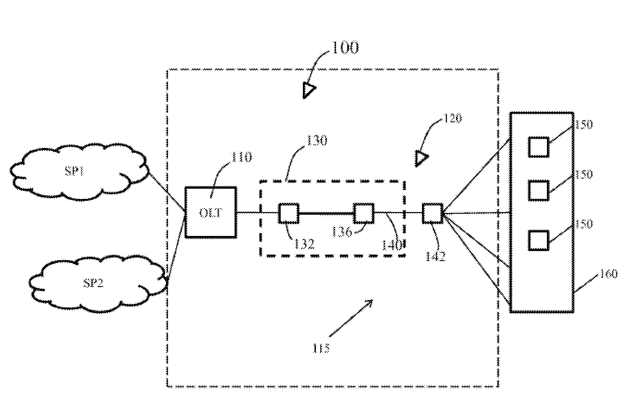
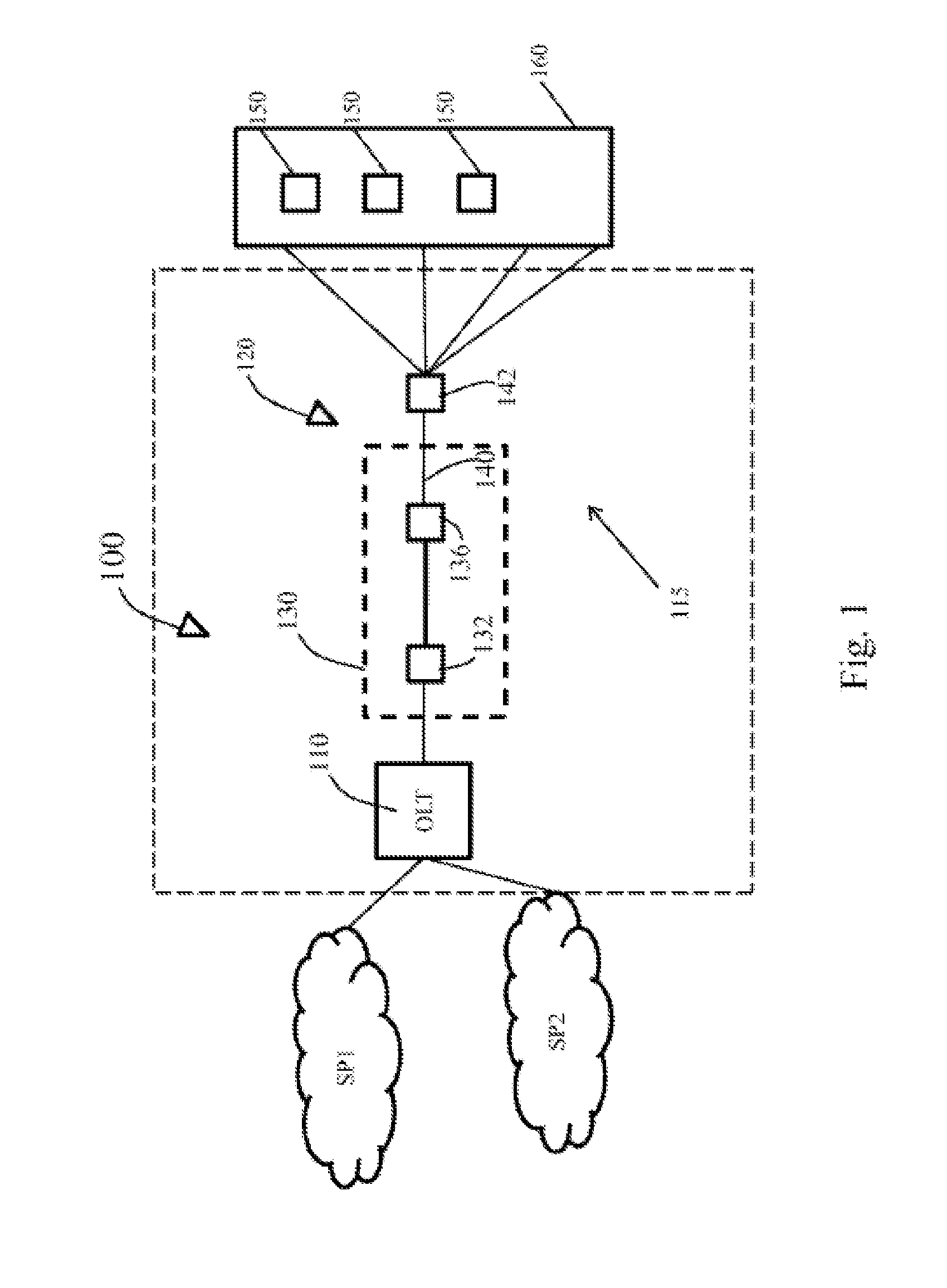
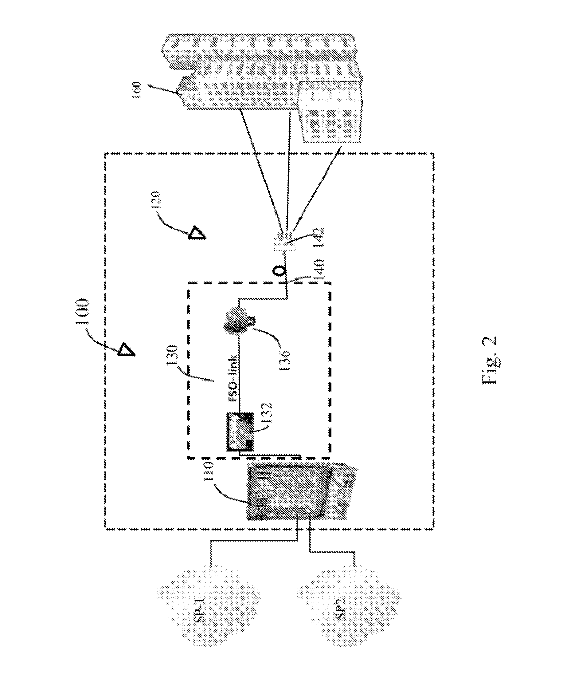
A system (100) for providing resilience in a communication network capable of providing multiple services to multiple customers. The system (100) includes at least one Optical Line Terminal (OLT) (110), and at least one Passive Optical Network (PON) based architecture (115) operably coupled to the at least one OLT (110). The PON based architecture (115) includes at least one down link mechanism (120) operably coupled to the at least one OLT (110). The down link mechanism (120) is capable of transporting optical signals generated by the OLT (110) downstream to users end via the PON based architecture (115) and includes at least one Free Space Optics (FSO) Link (130) configured to operate in a continuous mode both during up linking and down linking. The down link mechanism (120) provides the resilience in the communication network.

Description

FIELD OF THE DISCLOSURE[0001]This invention relates to optical networks, and more particularly, to an improved technique for providing resilience in communication networks, such as passive optical networksBACKGROUND OF THE DISCLOSURE[0002]Optical networks, such as Passive optical networks (PONs) and Ethernet passive optical networks (EPON), are commonly used in the present world for providing a variety of services, like telephony, cable television and internet, simultaneously to subscribers. A typical PON consists of an Optical line termination (OLT) at a service provider's office and a number of Optical Network Units (ONTs) near end users. The ONTs de-multiplex the optical signal received from the service provider into its various components, viz. telephony, cable television and data. The optical signal is transmitted to the ONTs through a fibre optic cable while the demultiplexed component signals from the ONTs are transmitted to the subscriber's home devices by using various outp...

Claims


Application Information

Patent Timeline
IPC IPC(8): H04B10/03H04B10/11H04B10/27
CPCH04B10/03H04B10/11H04B10/27H04J14/0282H04Q11/0067H04Q2011/0081H04B10/112H04B10/272
Inventor JAIN, VIJAY
Owner STERLITE NETWORKS LIMTED
Learn More