
MALDI Imaging and Ion Source

a technology of ion source and maldi, which is applied in the field of maldi imaging and ion source, can solve the problems of preventing the possibility of locating laser optics designed specifically, the size of the laser pulse incident on the sample is the angle of incidence of the laser beam, and the region that is irradiated quickly

Active Publication Date: 2015-02-05
MICROMASS UK LTD
View PDF14 Cites 31 Cited by
  • Summary
  • Abstract
  • Description
  • Claims
  • Application Information

AI Technical Summary

Benefits of technology

This patented technology allows for maintaining specific levels of electricity on certain parts of different conductors within a vacuum chamber during manufacturing processes. It uses special devices that can generate multiple types of electrical fields called transients with varying strengths over time. These techniques help improve the performance of these components by causing them to move towards each other smoothly without getting stuck together too much when they are moving slowly through narrow spaces like air pipes.

Problems solved by technology

The technical problem addressed in this patent text is to improve the spatial resolution of mass spectrometers using MALDI techniques by reducing the size of the laser pulse incident on the sample. This is achieved by ensuring that the laser beam is orthogonally incident upon the sample target and by using electrodes in close proximity to the sample to transfer the analyte ions formed in the MALDI plume into the analyzer.

Method used


Image

  • MALDI Imaging and Ion Source
  • MALDI Imaging and Ion Source
  • MALDI Imaging and Ion Source

Examples


Embodiment Construction

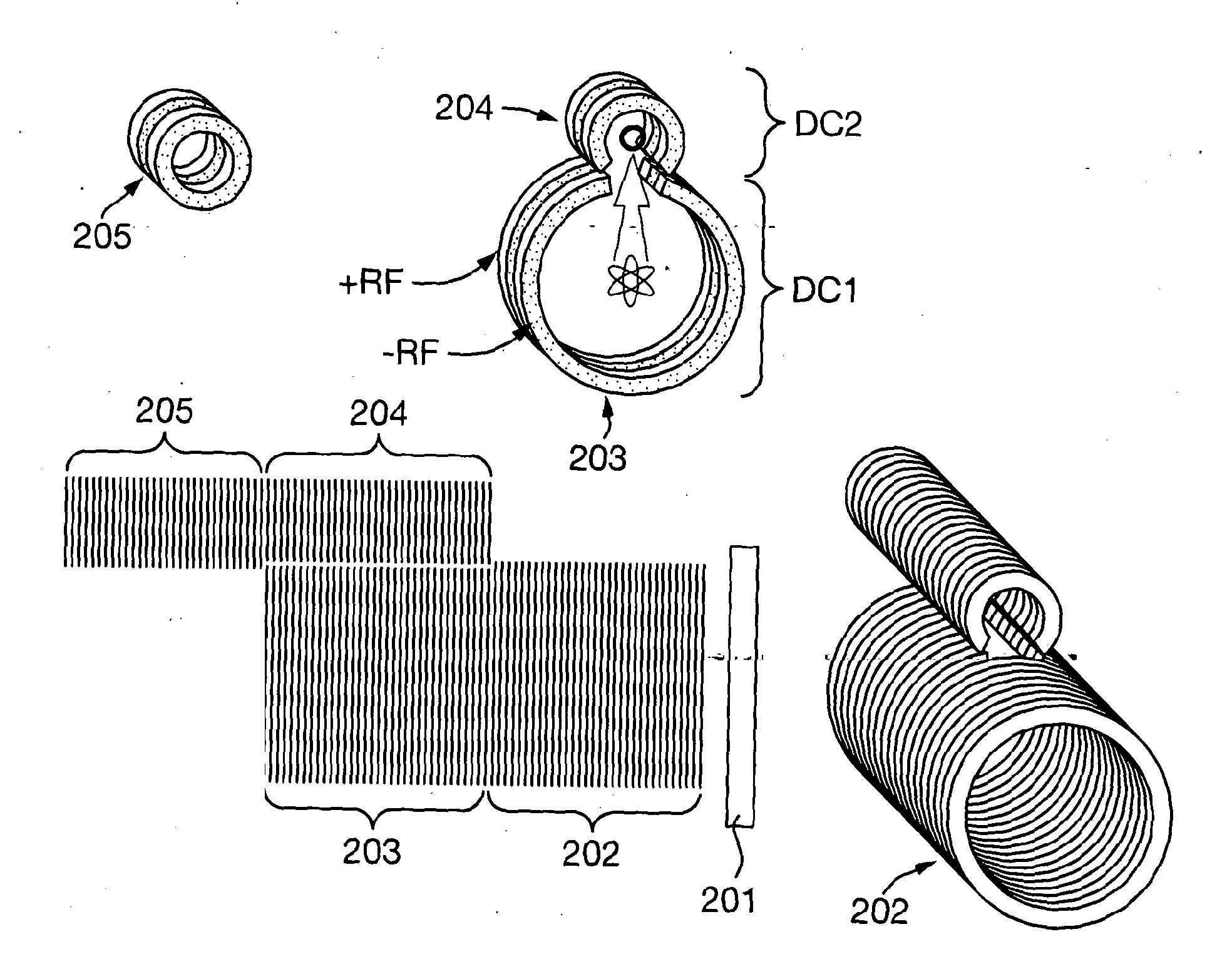
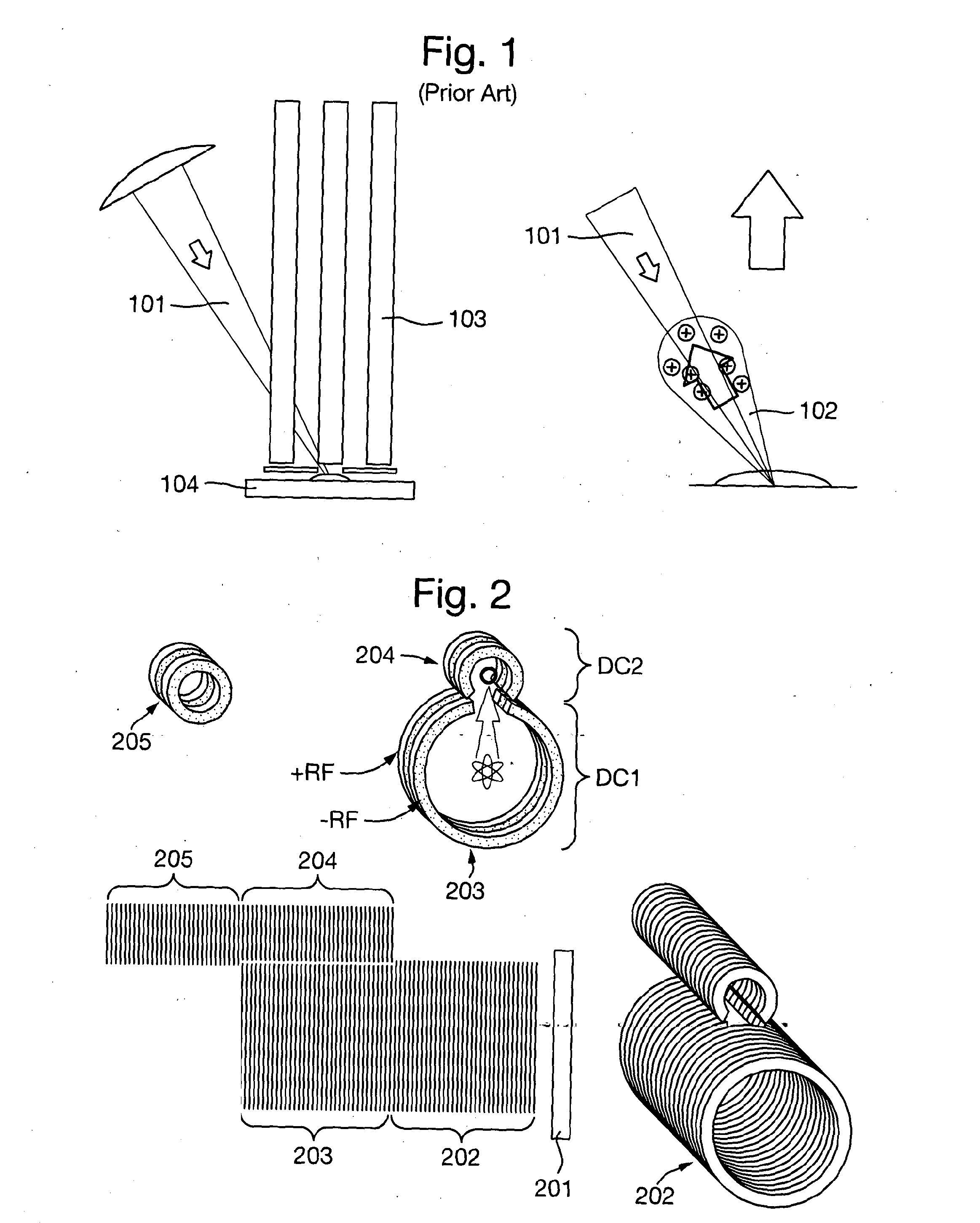
[0191]A known arrangement will first be described. FIG. 1 shows a known arrangement wherein a MALDI sample is illuminated by a laser beam 101. The angle of incidence of the beam determines the dominant direction of emission of the resulting plume of material 102. A multipole ion guide 103 is located adjacent the target substrate and has an on guiding region.

[0192]The plume 102 and the analyte ions formed subsequent to irradiation by the laser 101 tend to expand in a direction towards the incident laser beam 101. This is due to the inhomogeneous surface topography of the MALDI sample and crystalline matrix. Reference is made to P. Aksouh et al. Rapid Commun. Mass Spectrometry, 9 (1995) 515.

[0193]The ions formed in the MALDI plume must be transferred into the analyser requiring electrodes to be located in close proximity to the sample target. In high vacuum MALDI instruments, the requirement for electrostatic lenses to be also arranged along the ion optic axis to enable ion accelerati...


PUM


Abstract

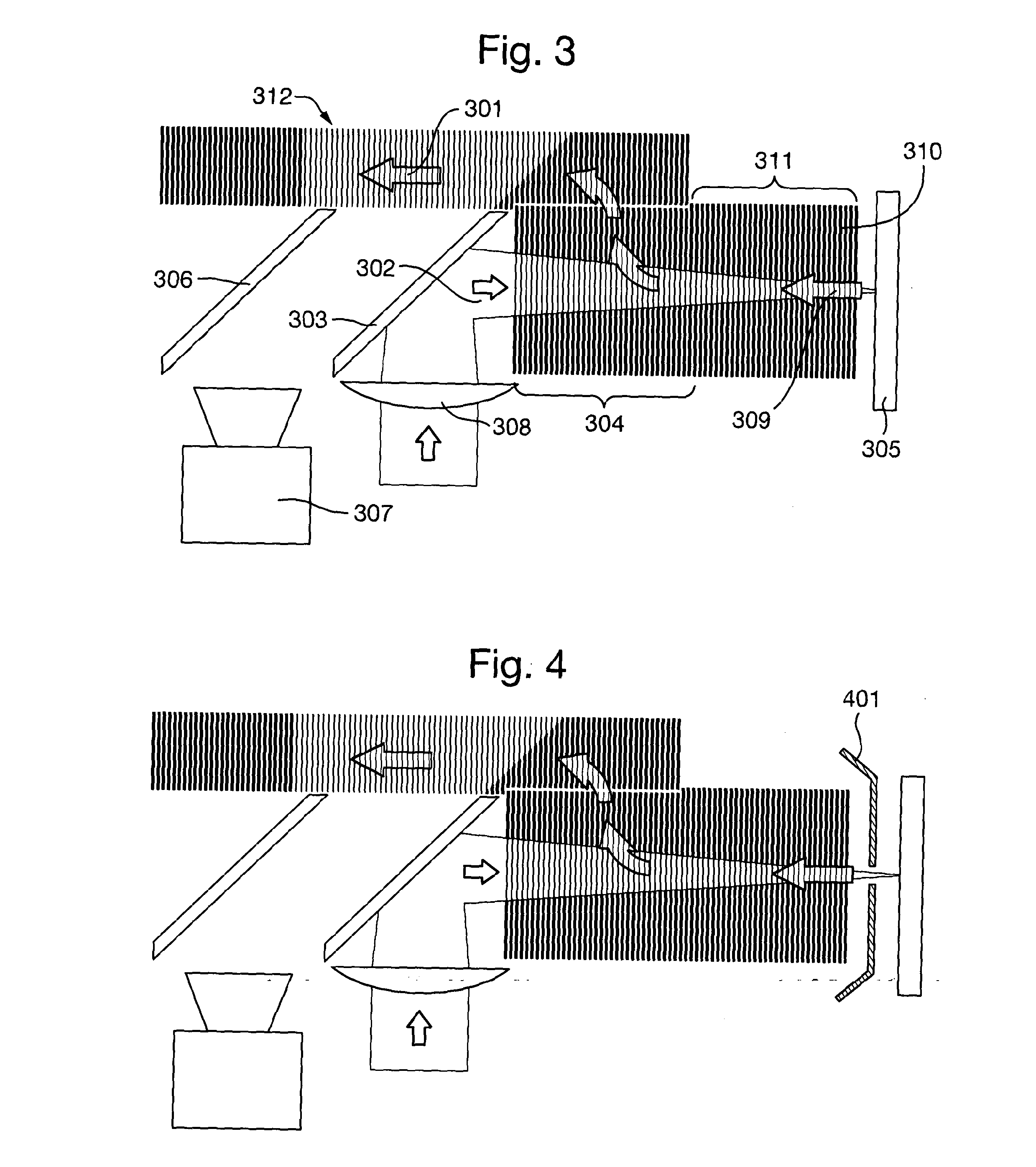
An ion source for a mass spectrometer is disclosed comprising a lens and mirror arrangement which focuses a laser beam onto the upper surface of a target substrate. The lens has an effective focal length ≦300 mm. The laser beam is directed onto the target substrate at an angle θ with respect to the perpendicular to the target substrate, wherein θ≦3°. One or more ion guides receive ions released from the target substrate and onwardly transmit the ions along an ion path which substantially bypasses the lens and mirror.

Description


Claims


Application Information

Patent Timeline
Owner MICROMASS UK LTD
Learn More