
Electronic device with environmental monitoring

a technology of environmental monitoring and electronic devices, applied in the direction of coupling device connections, optical radiation measurement, instruments, etc., can solve the problems of affecting the entry and change of barriers, affecting the ability of people to access the internet, and unable to enhance computing capabilities of electronic devices in the background

Active Publication Date: 2015-01-22
LEEO
View PDF5 Cites 37 Cited by
  • Summary
  • Abstract
  • Description
  • Claims
  • Application Information

AI Technical Summary

Benefits of technology

The described mounting system allows for easy and secure mounting of an electronic device to an external surface. The mounting system includes a base that can be attached to a wall or other external surface, and a mating surface on the electronic device that can be securely coupled to the base. The mounting system uses magnet coupling elements on the base and the electronic device to create a secure and adjustable connection. The system also allows for easy decoupling of the magnet coupling elements, as well as monitoring of spatial parameters and alerts when a change in the parameter exceeds a certain threshold. The mounting system can be used with various types of electronic devices and is suitable for both mechanical and magnetic coupling.

Problems solved by technology

However, the overwhelming majority of the existing background electronic devices in people's homes, offices and vehicles have neither enhanced computing capabilities (such as processor that can execute a wide variety of applications) nor networking subsystems.
These barriers to entry and change are obstacles to widely implementing the Internet of things.
As a consequence, it may also be difficult to extend the advantages of connectivity and enhanced computing capabilities into these environments.
In addition, many of the existing background electronic devices used in people's homes, offices and vehicles are difficult to use.
For example, it is often challenging to replace a battery or to modify the functions of these existing background electronic devices.

Method used


Image

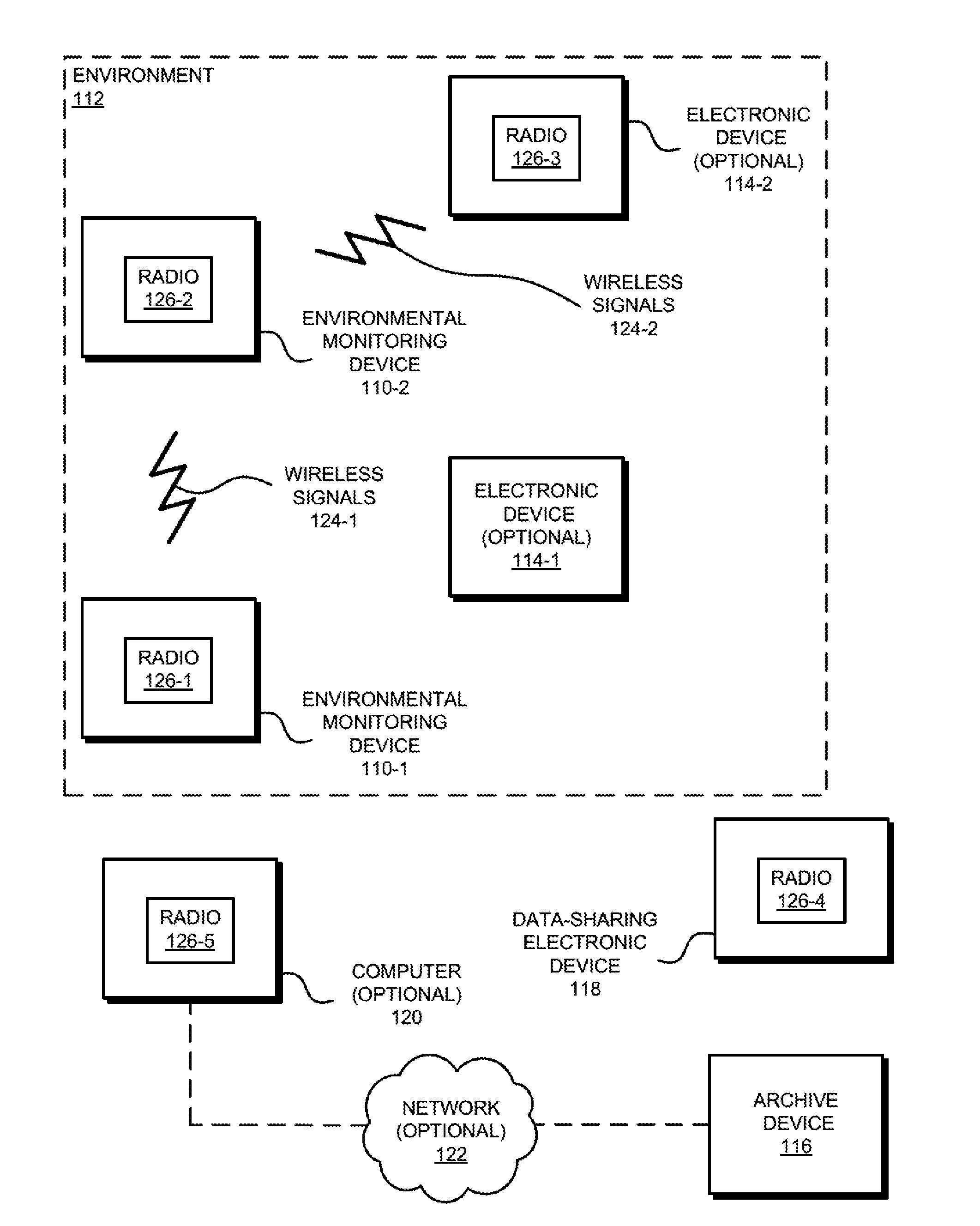
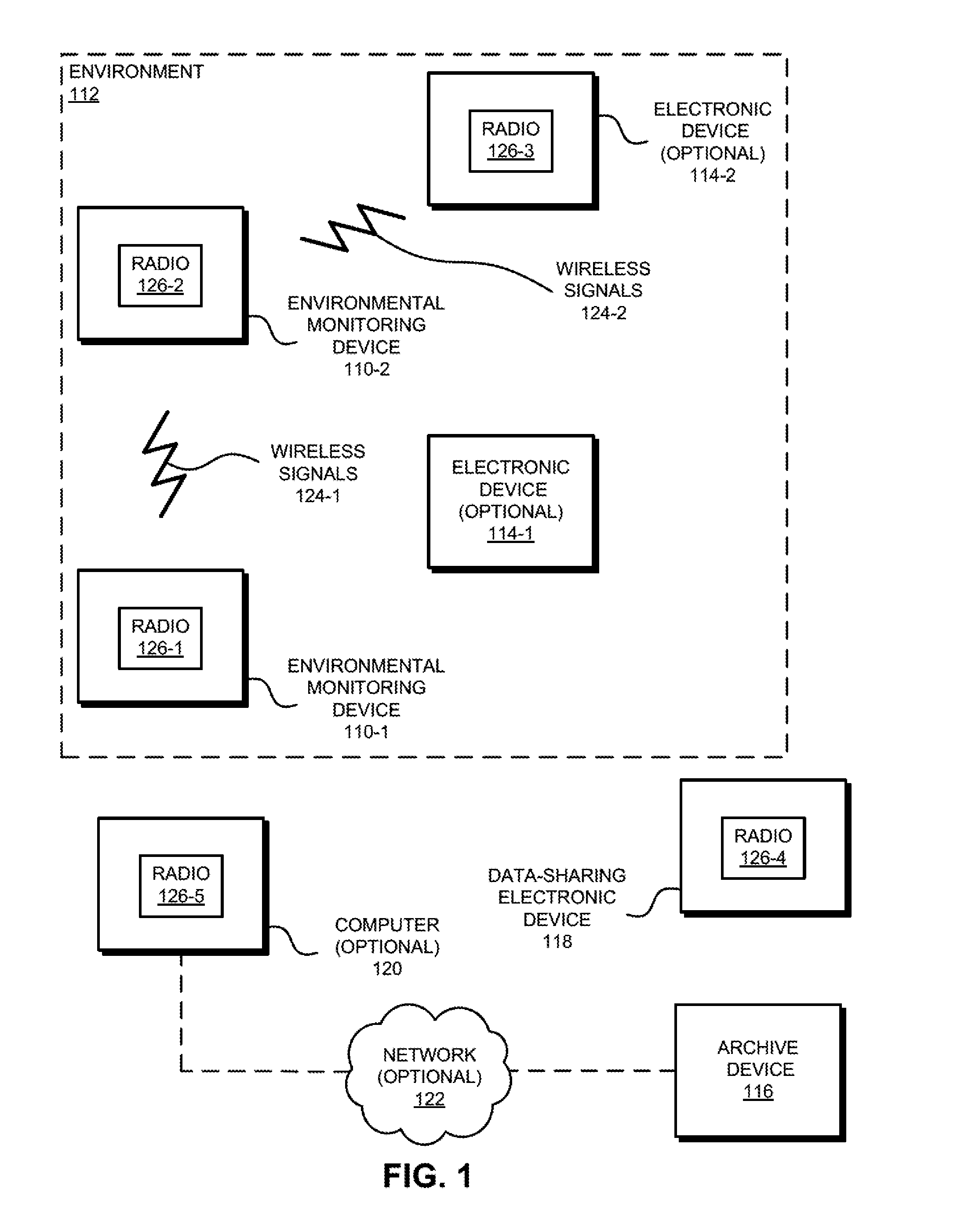
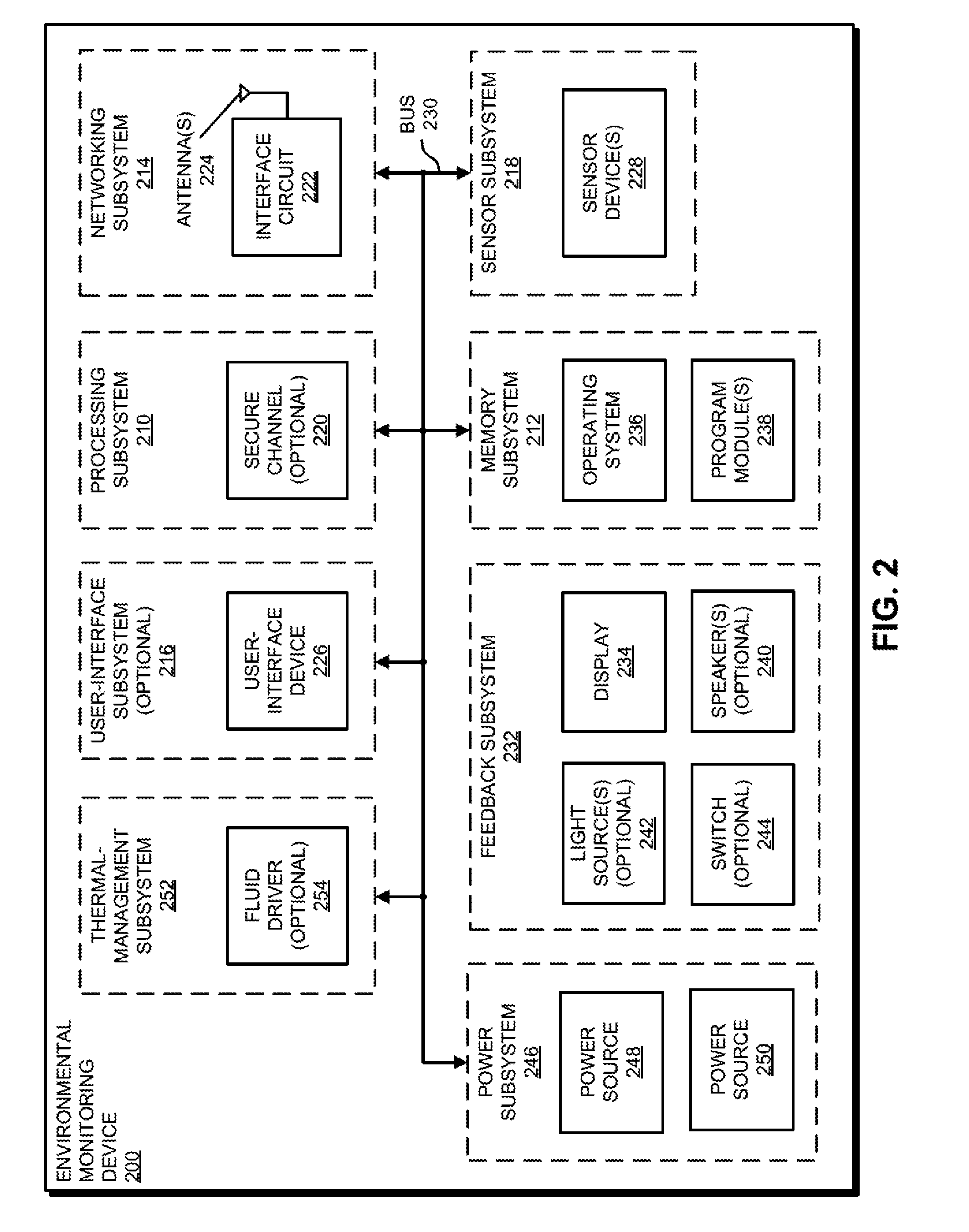
  • Electronic device with environmental monitoring
  • Electronic device with environmental monitoring
  • Electronic device with environmental monitoring

Examples


Embodiment Construction

[0057]A mounting system for an electronic device is described. This mounting system includes a base that can be rigidly mounted on or underneath a wall. Moreover, the base can be remateably coupled to the electronic device. The remateable coupling may involve pins that are inserted into corresponding holes and rotated into a lock position. Alternatively, the remateable coupling may involve magnets that mechanically couple to each other so long as the electronic device and the base are within a predefined distance. The electronic device may receive power via the remateable coupling or via inductive charging. In addition, the electronic device may monitor a spatial parameter, such as: a location of the electronic device, a velocity of the electronic device and / or an acceleration of the electronic device. If this spatial parameter changes without the electronic device first receiving a security code, the electronic device provides an alert.

[0058]In this way, the mounting system may fac...


PUM


Abstract

A mounting system for an electronic device is described. This mounting system includes a base that can be rigidly mounted on or underneath a wall. Moreover, the base can be remateably coupled to the electronic device. The remateable coupling may involve pins that are inserted into corresponding holes and rotated into a lock position. Alternatively, the remateable coupling may involve magnets that mechanically couple to each other so long as the electronic device and the base are within a predefined distance. The electronic device may receive power via the remateable coupling or via inductive charging. In addition, the electronic device may monitor a spatial parameter, such as: a location of the electronic device, a velocity of the electronic device and / or an acceleration of the electronic device. If this spatial parameter changes without the electronic device first receiving a security code, the electronic device provides an alert.

Description

CROSS REFERENCE TO RELATED APPLICATION[0001]This application is a divisional of U.S. patent application Ser. No. 14 / 283,097 filed May 20, 2014 which claims priority under 35 U.S.C. §119(e) to: U.S. Provisional Application Ser. No. 61 / 847,079, entitled “Lighting Device with Environmental Monitoring System,” by Adam M. Gettings, Eddy Y. Chan, Andrew G. Stevens, and Bjorn H. Hovland, filed on Jul. 16, 2013; U.S. Provisional Application Ser. No. 61 / 847,555, entitled “Safety Detector with Environmental Monitoring System,” by Adam M. Gettings, Eddy Y. Chan, Andrew G. Stevens, and Bjorn H. Hovland, filed on Jul. 17, 2013; and U.S. Provisional Application Ser. No. 61 / 858,563, entitled “Switch with Environmental Monitoring System,” by Adam M. Gettings, Eddy Y. Chan, Andrew G. Stevens, and Bjorn H. Hovland, filed on Jul. 25, 2013, the contents of all of which are herein incorporated by reference.BACKGROUND[0002]1. Field[0003]The described embodiments relate generally to an environmental monit...

Claims


Application Information

Patent Timeline
Patent Type & Authority Applications(United States)
IPC IPC(8): G08B13/02H01R13/62
CPCH01R13/6205G08B13/02G08B21/18G01D7/00G01D11/245G01F1/00G01J1/0437G01J1/42G01N21/84G01N33/00G01N33/0031G08B3/00G08B3/10G08B17/10G08B19/005G08B21/12G08B29/181H01R13/627G08B21/14G08B17/113G01N33/0075
Inventor GETTINGS, ADAM MATTHEWSTEVENS, ANDREW GETTINGSHOVLAND, BJORN
Owner LEEO
Learn More