
Detection circuit for display panel

Inactive Publication Date: 2015-01-22
TCL CHINA STAR OPTOELECTRONICS TECH CO LTD
View PDF12 Cites 12 Cited by
  • Summary
  • Abstract
  • Description
  • Claims
  • Application Information

AI Technical Summary

Benefits of technology

The present disclosure aims to provide a panel detection circuit that can prevent interference with a display panel during operation. The disclosure introduces a component that reduces voltage on the gates of a transistor array to reliably cut off the transistor array when a low-level signal is applied. This reduces leakage currents and improves the detection circuit's reliability. Additionally, the disclosure shares connection lines for both a control signal and a test signal, preventing interference with the normal operation of the display panel. Finally, the detection circuit reduces the channel length of the TFT, advantageous for designing a narrow frame.

Problems solved by technology

However, under some circumstances, the removal out or laser out is not very convenient.
If the test circuit is reserved, leakage currents exist between the sources and the drains of components such as TFT (thin film transistor) switches in the test circuit, which interfere with the data lines and gate lines of the display area.
But by doing so, it is disadvantageous for the design of a narrow frame.

Method used


Image

  • Detection circuit for display panel
  • Detection circuit for display panel
  • Detection circuit for display panel

Examples


Embodiment Construction

[0024]The embodiments of the present disclosure will be illustrated in detail in conjunction with the accompanying drawings and embodiments, and thus how to use technical means to solve the technical problems and the implementation process of achieving the technical effects may be fully understood and accordingly implemented. It should be noted that as long as conflicts are avoided, all embodiments in the present disclosure and all features in all the embodiments may be combined together, and the formed technical solutions are within the scope of the present disclosure.

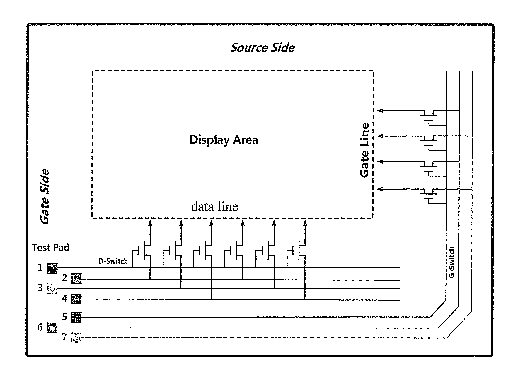
[0025]FIG. 1 shows a schematic diagram of a detection circuit. In FIG. 1, test pads 1-7 each are connected to the data lines and the scanning lines of the display panel via a digital switch array (for example, a TFT switch array) and wires (or connection lines) on a shorting bar. The digital switch array is not limited to the TFT switch array, and other controllable digital switch arrays such as a transistor array can...


PUM


Abstract

The present disclosure provides a detection circuit for a display panel, comprising: a shorting bar, with connection lines for introducing a test signal or a control signal arranged thereon; a transistor array, the gates of which are connected to the connection lines for introducing the control signal, wherein the connection lines for introducing the test signal are connected with the data lines or the scanning lines of the display panel via the sources and the drains of transistors, under the control signal, and a component, arranged between the gates of the transistor array and the shorting bar, for further reducing or increasing a voltage or current of the gates so that the transistor array can be cut off reliably when the control signal is a signal enabling the transistor array to be cut off. The detection circuit can further reduce the channel length of the thus being advantageous for the design of the narrow frame.

Description

FIELD OF THE INVENTION[0001]The present disclosure relates to the field of display technologies, and particularly relates to a detection circuit for a display panel.BACKGROUND OF THE INVENTION[0002]In the process of manufacturing a thin film transistor-liquid crystal display (TFT-LCD) panel, specifically in the phases of manufacturing an array and a cell, the yield of the liquid crystal panel is generally monitored through a test such as light-on testing. Connection between a test circuit and circuits on a display area can be removed out or laser out after a test. However, under some circumstances, the removal out or laser out is not very convenient. If the test circuit is reserved, leakage currents exist between the sources and the drains of components such as TFT (thin film transistor) switches in the test circuit, which interfere with the data lines and gate lines of the display area. In one case, for preventing the leakage currents of the TFT switches in a cut-off state, the cha...

Claims


Application Information

Patent Timeline
IPC IPC(8): G09G3/00
CPCG09G3/006
Inventor DU, PENGHSU, JE-HAOSHIH, MING-HUNG
Owner TCL CHINA STAR OPTOELECTRONICS TECH CO LTD
Learn More