
Filament winding method and filament winding apparatus

a technology of winding method and filament, which is applied in the direction of filament handling, thin material processing, transportation and packaging, etc., can solve the problems of inability to detect the winding speed, inability to obtain a bobbin diameter, and inability to wind filament, so as to reduce the effort and time required by the operator, reduce the variation of the measured bobbin diameter, and achieve the effect of forming a reinforcing fiber preform

Active Publication Date: 2015-01-22
JTEKT CORP +1
View PDF1 Cites 6 Cited by
  • Summary
  • Abstract
  • Description
  • Claims
  • Application Information

AI Technical Summary

Benefits of technology

The patent describes a filament winding method and apparatus that can automatically detect the diameter of a bobbin on which filament is wound, without the need for an operator to manually measure it. This is achieved by oscillating the dancer (a device used to control the rotation of the bobbin) from one end of its range to the other, allowing for a wider range of measurements that can account for variations in the bobbin's position. By doing so, the method and apparatus can automatically adjust settings and control the rotation speed of the bobbin, resulting in more accurate and consistent measurements, and reducing the burden on the operator and costs.

Problems solved by technology

However, when a new bobbin is mounted on the filament winding apparatus, filament is not unwound yet.
Therefore, it is not possible to detect unwinding speed and rotation speed of the bobbin and it is thus impossible to obtain a bobbin diameter.
Manual measurement of a bobbin diameter by an operator is not preferred because a burden is imposed on the operator and measurement results vary.
However, since it is necessary to mount the winding bobbin diameter detecting means on an appropriate position in the filament winding apparatus, efforts, time and costs are required, which is not preferred.

Method used


Image

  • Filament winding method and filament winding apparatus
  • Filament winding method and filament winding apparatus
  • Filament winding method and filament winding apparatus

Examples


Embodiment Construction

[0026]A mode for carrying out the invention is explained below by using the drawings.

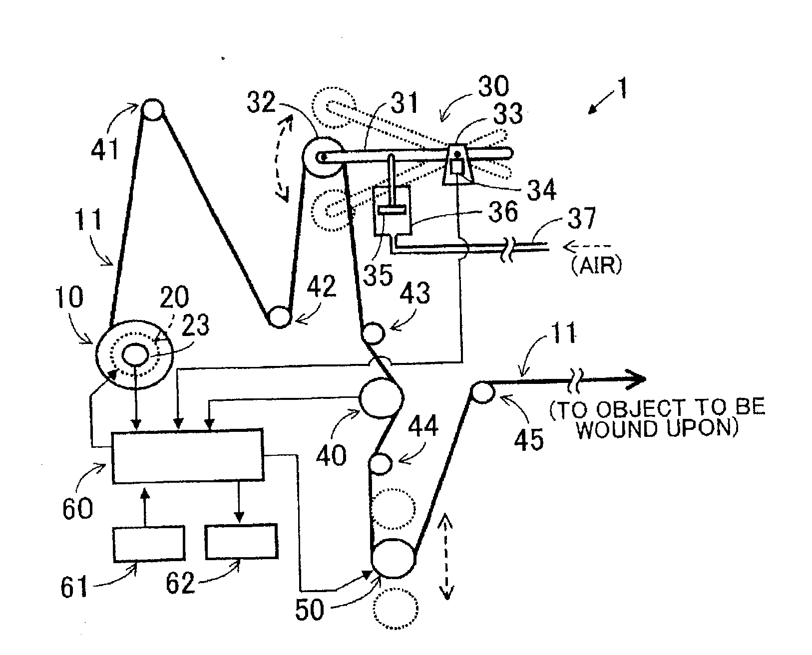
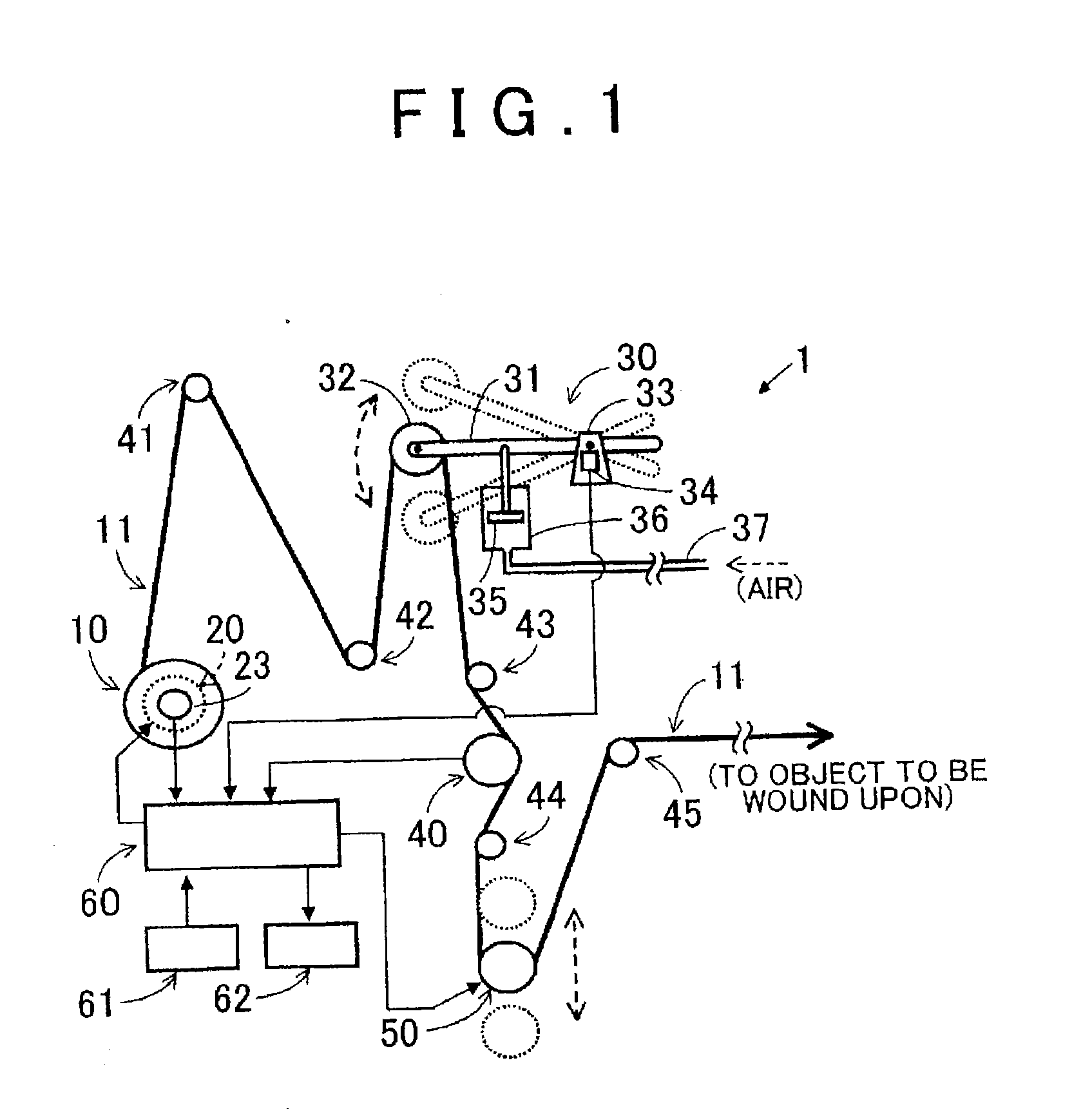
[0027]First of all, an overall structure of a filament winding apparatus 1 is explained by using FIG. 1. The filament winding apparatus 1 is provided with a bobbin rotation driving device 20, guide rollers 41 to 45, a dancer 30, a measuring roller 40, an active dancer roller 50, a control device 60, an input device 61, a display device 62 and so on. The filament is linear fiber such as ceramic fiber, glass fiber, and carbon impregnated in a resin.

[0028]The bobbin rotation driving device 20 is, for example, an electric motor. A bobbin 10, on which the filament is wound, is mounted on the bobbin rotation driving device 20. The bobbin rotation driving device 20 is driven by a control signal from the control device 60 and rotates the mounted bobbin 10. Rotation speed, a rotation angle, and so on are outputted from a rotation detection device 23 such as an encoder (an example of a rotation angle detectio...


PUM


Abstract

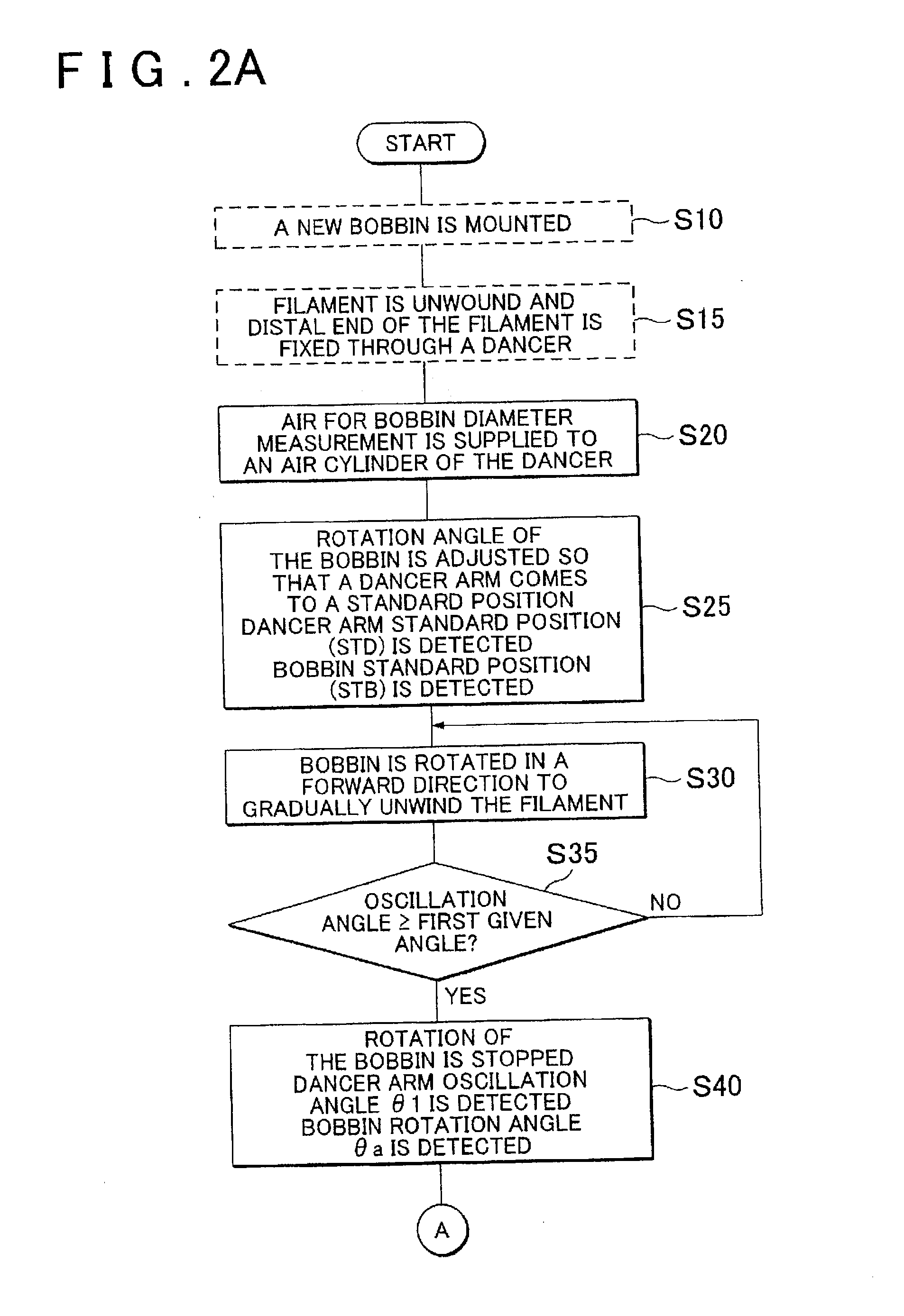
Provided are a filament winding method and a filament winding apparatus, in which, when a new bobbin is mounted on a bobbin rotation driving device, the control device is programmed to rotate the bobbin and oscillate a dancer while maintaining a state where a distal end of filament unwound through the dancer is fixed further beyond the dancer and the filament is stretched. The control device is programmed to obtain a bobbin diameter of the bobbin mounted on the bobbin rotation driving device based on a length of the dancer, an oscillation angle of the dancer, and a rotation angle of the bobbin.

Description

INCORPORATION BY REFERENCE[0001]The disclosure of Japanese Patent Application No. 2013-147360 filed on Jul. 16, 2013 including the specification, drawings and abstract is incorporated herein by reference in its entirety.BACKGROUND OF THE INVENTION[0002]1. Field of the Invention[0003]The invention relates to a filament winding method and a filament winding apparatus, by which filament such as ceramic fiber, glass fiber, and carbon fiber is unwound from a bobbin upon which the filament is wound.[0004]2. Description of Related Art[0005]In recent years, a method for forming a reinforcing fiber preform has been widely used, in which filament made by impregnating ceramic fiber, glass fiber, carbon fiber, or the like into a resin or the like is unwound at certain tension from a bobbin upon which the filament is wound, and the unwound filament is wound on an object to be wound upon. Also, a filament winding apparatus is used as an apparatus for unwinding the filament from the bobbin at cert...

Claims


Application Information

Patent Timeline
Patent Type & Authority Applications(United States)
IPC IPC(8): B65H59/36B65H59/38
CPCB65H59/36B65H59/387
Inventor YAMAGUCHI, YUJIKOJIMA, HISAKIOHTANI, TADASHIFUJII, TAKESHI
Owner JTEKT CORP
Learn More