System and method for integrating candidate implant location test results with real-time tissue images for use with implantable device leads

a technology for implantable devices and test results, applied in the field of systems, can solve the problems of multiple fixations around the same area, damage to tissue at the site, and difficulty for clinicians to know exactly which locations have already been tested, so as to facilitate the visualization of lead parameters and avoid cluttering the image

Active Publication Date: 2015-01-15
PACESETTER INC
View PDF2 Cites 4 Cited by
  • Summary
  • Abstract
  • Description
  • Claims
  • Application Information

AI Technical Summary

Benefits of technology

[0006]In an exemplary embodiment, a method is provided for use with an implantable medical lead system for implant within a patient. Briefly, tissues of the patient are imaged along with portions of the lead system being implanted using, e.g., a real-time fluoroscopic imaging system. One or more parameters representative of lead placement efficacy—such as myocardial capture thresholds. PNS thresholds, electrical impedance values or screw-in tip mechanical resistance values—are measured at candidate implant locations within the tissues of the patient using repositionable electrodes of the lead system. Localization parameters identifying the candidate implant locations are also measured. A display is generated showing: images of the tissues of the patient and at least a portion of the lead system being implanted; the candidate locations of the repositionable electrodes; and parameters representative of lead placement efficacy at the candidate locations such as capture thresholds or the mechanical resistance values. In some examples, the efficacy values are color-coded without showing actual numerical values. Moreover, thresholds may be set such that only “acceptable” sites based on the thresholds are highlighted. That is, thresholds can be used to facilitate the visualization of the lead parameters as a way to avoid cluttering of the image. In examples where sensor icons are displayed, the icons may also change color to indicate acceptable or non-acceptable lead parameters to thereby aid the visualization of the localization parameters on the images. Using these or other visualization techniques, the implanting clinician can readily view capture thresholds and / or icons and other helpful parameters at various candidate implant locations along with actual images of the tissues of the patient and the lead system being implanted. Preferably, real-time or near real-time images are used, although recorded images can also be displayed and, in some examples, multiple images can be superimposed over one another, some in real-time and some recorded.

Problems solved by technology

However, the two-dimensionality of conventional fluoroscopic images can make it difficult for the clinician to know exactly which locations have already been tested.
This can be especially problematic if an active fixation lead needs to be inserted into cardiac tissue with each test, damaging the tissue at the site.
Multiple fixations around the same area can be life-threatening, especially within the thin-walled chambers of the heart such as the RA and RV.
Still further, some implant locations might have residual scar tissue due to myocardial infarction or other conditions, which can render the location undesirable for implantation, a problem not readily discernible from standard fluoroscopic images.

Method used


Image

  • System and method for integrating candidate implant location test results with real-time tissue images for use with implantable device leads
  • System and method for integrating candidate implant location test results with real-time tissue images for use with implantable device leads
  • System and method for integrating candidate implant location test results with real-time tissue images for use with implantable device leads

Examples


Embodiment Construction

[0019]The following description includes the best mode presently contemplated for practicing the invention. This description is not to be taken in a limiting sense but is made merely to describe general principles of the invention. The scope of the invention should be ascertained with reference to the issued claims. In the description of the invention that follows, like numerals or reference designators will be used to refer to like parts or elements throughout.

Overview of Systems and Methods

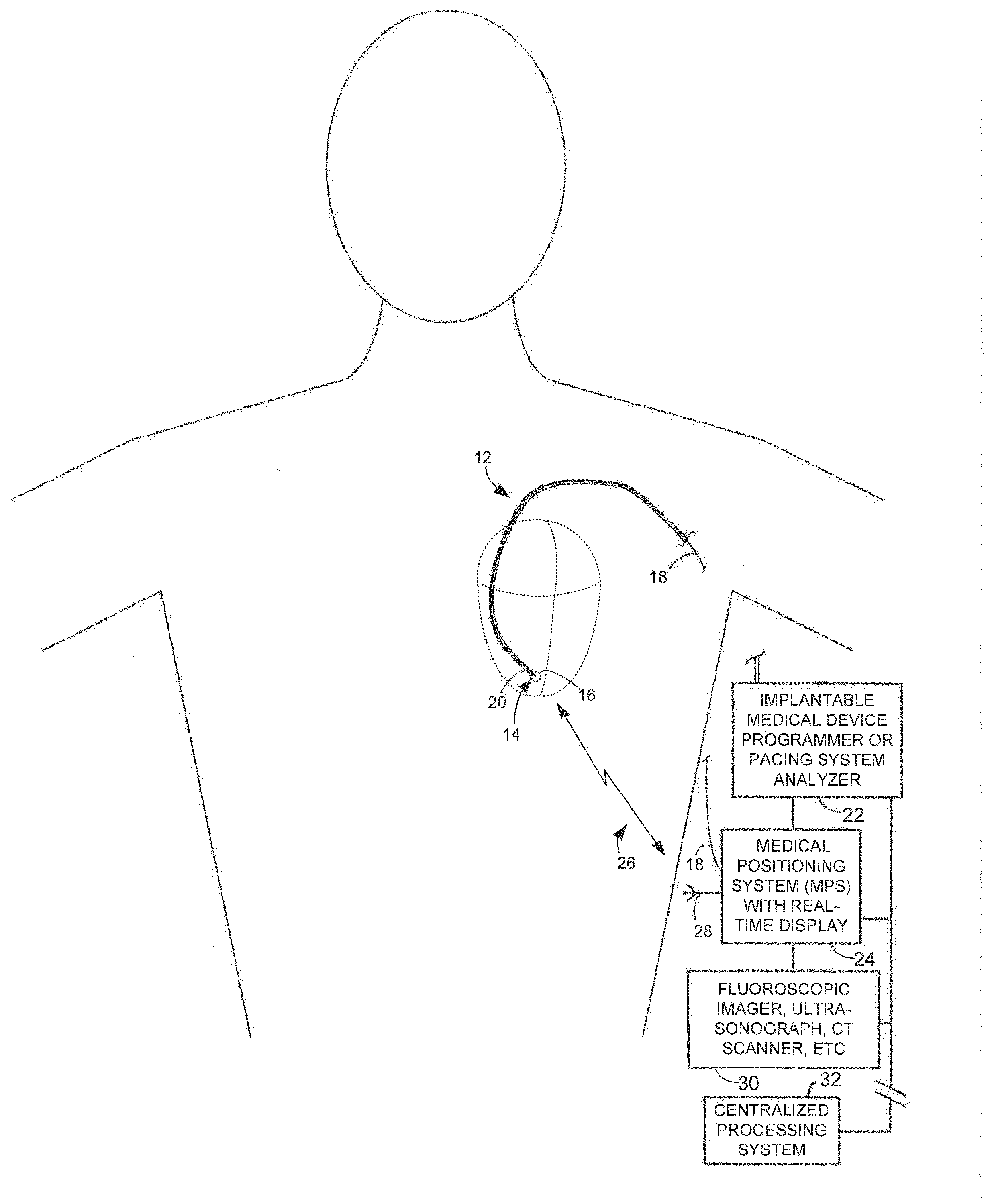
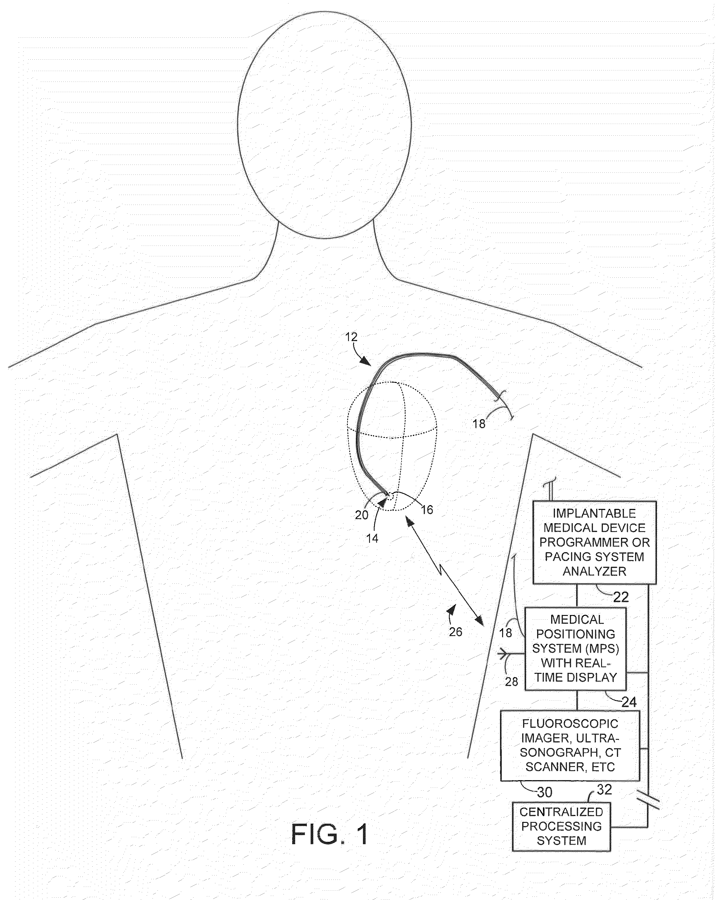
[0020]FIG. 1 provides a stylized illustration of pertinent portions of an implantable medical lead 12 having an active fixation tip electrode 14 for implant into the RV of the heart of a patient, with the lead shown positioned at a candidate implant location 16. (Note that, for clarity and simplicity, not all of the features of the RV lead are shown, such as its ring electrode or its shocking coil electrode or any physiological sensors that might be mounted to the lead. Also, note that other lea...


PUM


Abstract

Patient tissues are imaged using, e.g., a real-time fluoroscopic imaging system, along with a lead system being implanted. Parameters representative of lead placement efficacy—such as capture thresholds, phrenic nerve stimulation thresholds, impedance values or screw-in tip mechanical resistance values—are measured at candidate implant locations. Localization parameters identifying the candidate implant locations are also measured. In one example, a display is generated substantially in real-time showing: images of the tissues of the patient and the lead system being implanted: candidate locations of the electrodes; and parameters representative of lead placement efficacy at the candidate locations. In this manner, the implanting clinician can readily view capture thresholds and other helpful parameters at various candidate locations along with actual real-time images of the tissues of the patient and the lead system being implanted. Recorded images can also be displayed and, in some examples, multiple images can be superimposed over one another.

Description

FIELD OF THE INVENTION[0001]Aspects of the invention relate to device programmers for use with implantable medical devices and to medical positioning and display systems for use during implantation of the lead systems of such medical devices.BACKGROUND OF THE INVENTION[0002]Implantation of lead systems for pacemakers or other implantable medical devices often requires the testing of candidate lead locations for parameters such as myocardial capture thresholds, phrenic nerve stimulation thresholds, electrical impedance values, and the like. Herein, these and other related parameters are referred to as “lead implant efficacy parameters” since the parameters pertain to the efficacy or suitability of particular lead implant locations. In practice, the implanting clinician often tests a number of candidate implant locations while observing the location of the lead within the patient using fluoroscopic images or the like. At a particular candidate location, the clinician typically employs...

Claims


Application Information

Patent Timeline
Patent Type & Authority Applications(United States)
IPC IPC(8): A61B19/00A61N1/05
CPCA61N1/05A61B19/5244A61N1/056A61B34/20A61B34/25A61B2090/376A61B2090/3762A61B2034/2051A61B2090/378
Inventor RAZAVI, HEDIARNOLD, EDITHQU, FUJIANNABUTOVSKY, YELENA
Owner PACESETTER INC
Why Eureka
Try Eureka