
Pointing stick cursor key and illuminated keyboard therewith

a technology of illuminated keyboard and cursor key, which is applied in the direction of electric switches, electric instruments, legends, etc., can solve the problems of light leakage in a position, holes on the lateral walls, and problems in the appearance of illuminated keyboard, so as to reduce light leakage, enhance the visual feeling of illuminated keyboard, and reduce light leakage

Inactive Publication Date: 2015-01-15
DARFON ELECTRONICS (SUZHOU) CO LTD +1
View PDF0 Cites 6 Cited by
  • Summary
  • Abstract
  • Description
  • Claims
  • Application Information

AI Technical Summary

Benefits of technology

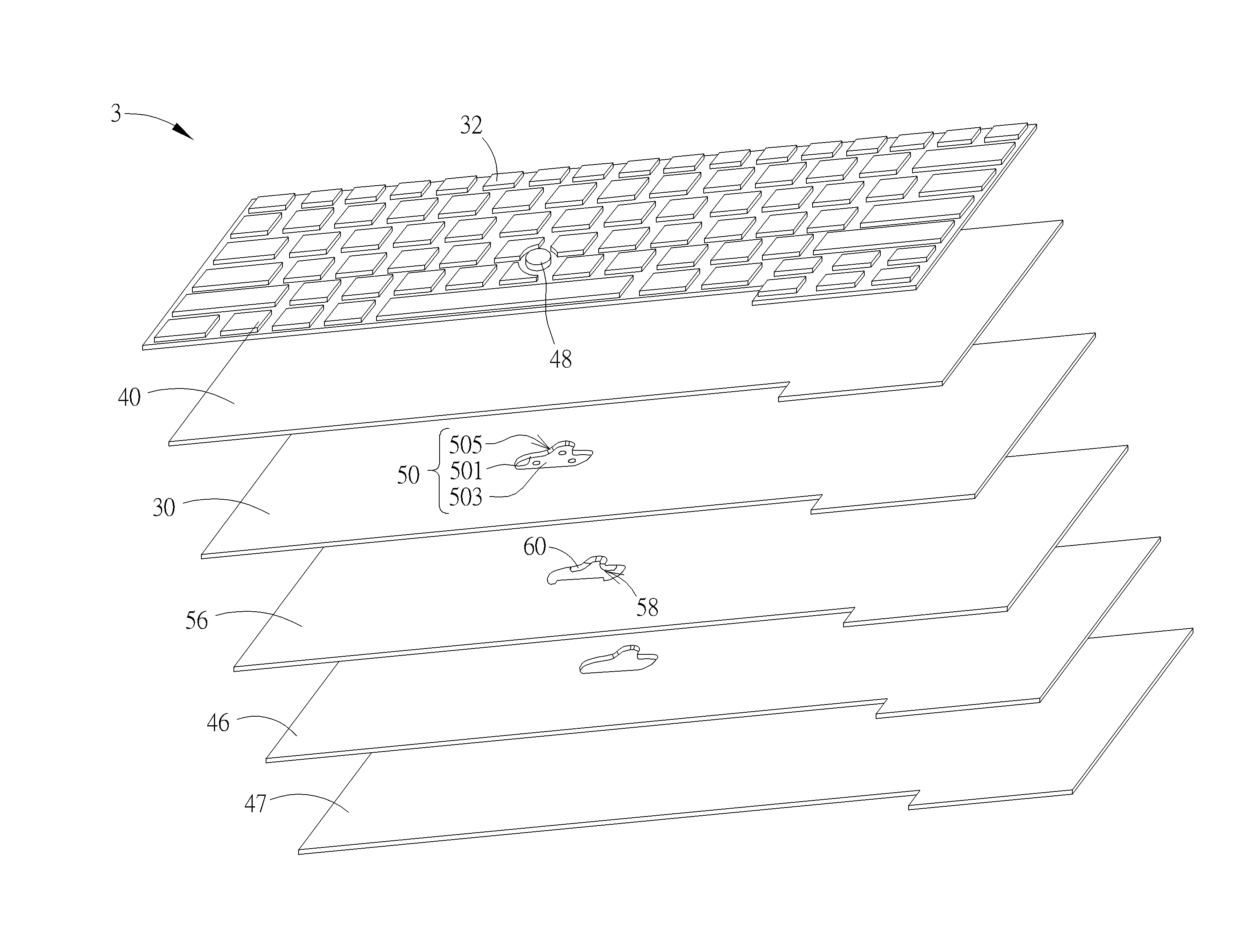
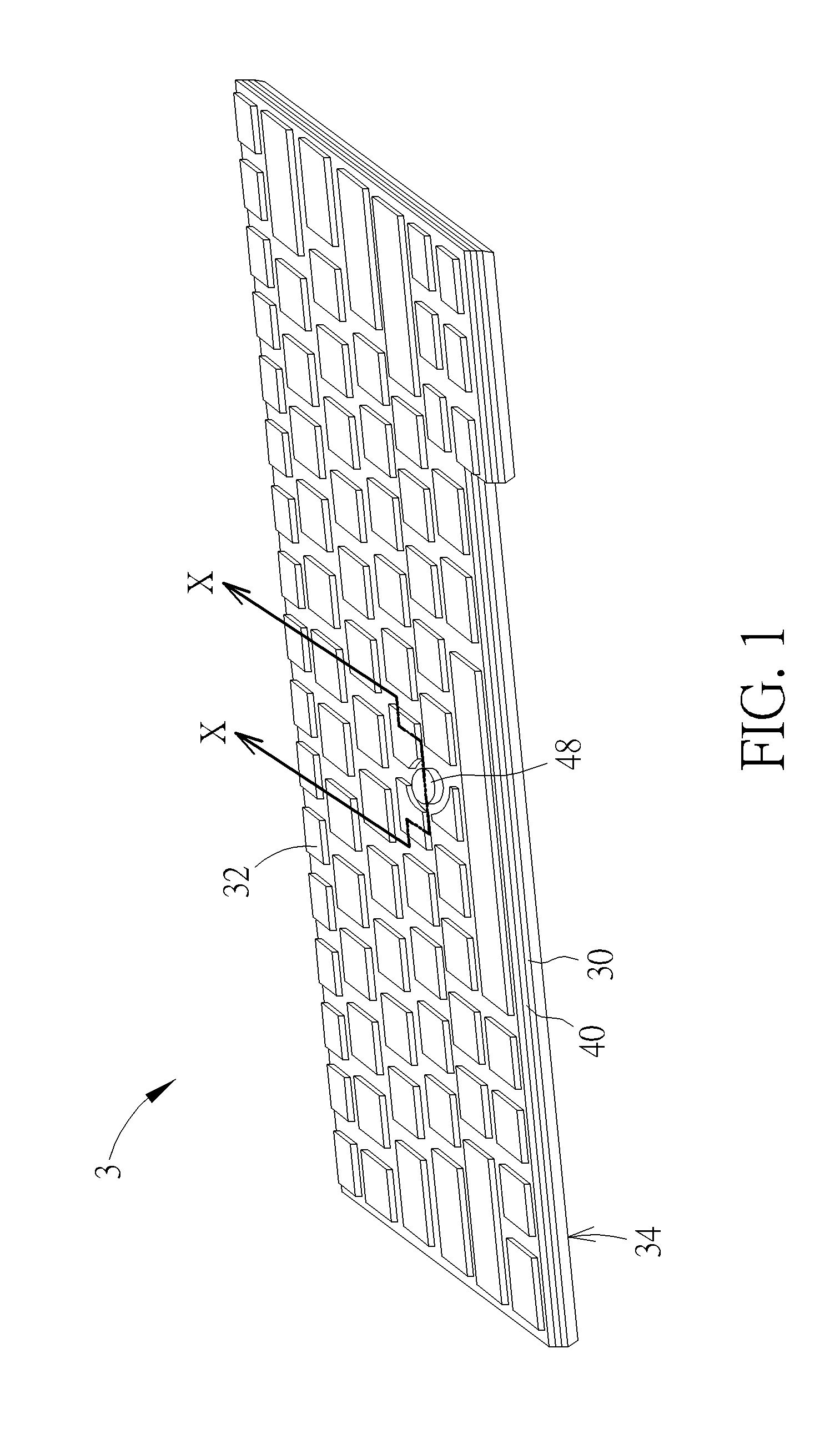
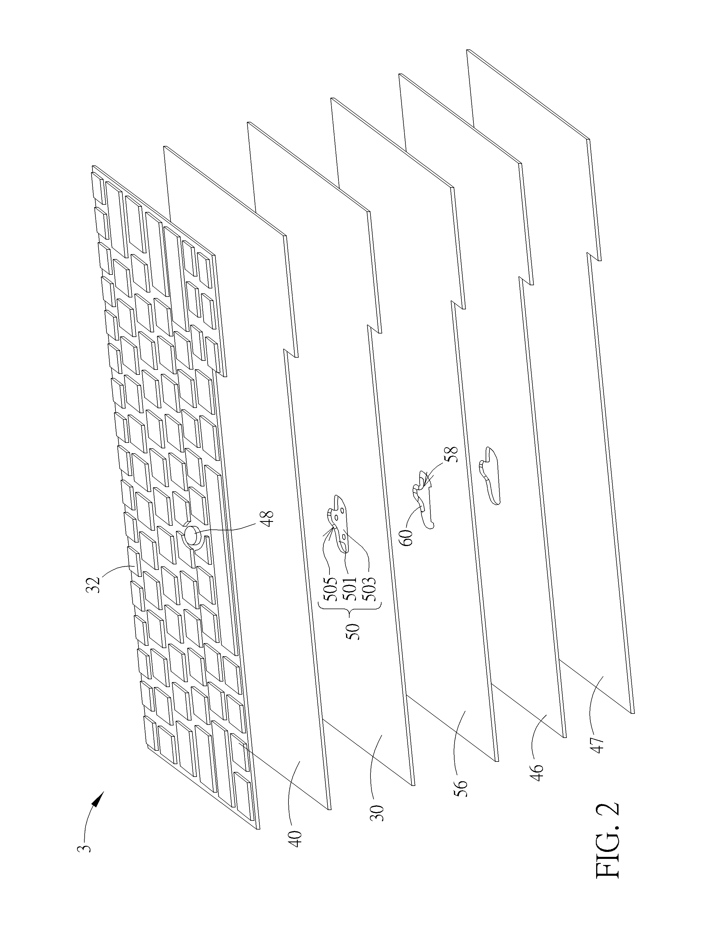
The present invention provides a pointing stick cursor key and an illuminated keyboard that can reduce light leakage and enhance the visual feeling of use. The pointing stick cursor key includes a holding structure, an opening, and at least one masking portion. The holding structure is extended into the backlight module via the opening, and the masking portion bendably abuts against the holding structure for masking the opening, so as to prevent a light emitted from the backlight module from projecting out from the other side of the base plate via the opening. The technical effect of the invention is to reduce light leakage in the position corresponding to the holding structure of the illuminated keyboard and enhance the visual feeling of use.

Problems solved by technology

In practical application, the aforesaid holding structure is a recessed structure, and it often results in holes on the lateral walls thereof due to thickness of the base plate as being stamped.
As a result, a light generated from the backlight module of the illuminated keyboard can project out of the illuminated keyboard via the holes, leading to light leakage in a position corresponding to the holding structure of the illuminated keyboard.
Therefore, the leakage light causes issues in appearance of the illuminated keyboard.

Method used


Image

  • Pointing stick cursor key and illuminated keyboard therewith
  • Pointing stick cursor key and illuminated keyboard therewith
  • Pointing stick cursor key and illuminated keyboard therewith

Examples


Embodiment Construction

[0015]In the following detailed description of the embodiments, reference is made to the accompanying drawings which form a part hereof, and in which is shown by way of illustration specific embodiments in which the invention may be practiced. In this regard, directional terminology, such as “top,”“bottom,” etc., is used with reference to the orientation of the Figure(s) being described. The components of the present invention can be positioned in a number of different orientations. As such, the directional terminology is used for purposes of illustration and is in no way limiting. On the other hand, the drawings are only schematic and the sizes of components may be exaggerated for clarity. It is to be understood that other embodiments may be utilized and structural changes may be made without departing from the scope of the present invention. Also, it is to be understood that the phraseology and terminology used herein is for the purpose of description and should not be regarded as...


PUM


Abstract

The illuminated keyboard includes a base plate, a backlight module, a plurality of input keys and a mask layer. The backlight module and the plurality of input keys are disposed on opposite sides of the base plate. The mask layer is disposed between the base plate and the backlight module. A pointing stick cursor key includes a holding structure, an opening and a masking portion. The holding structure with a hole is disposed on the base plate. The opening is formed on the mask layer in a position corresponding to the holding structure. The holding structure is extended into the backlight module via the opening. The at least one masking portion is connected to a periphery of the opening for bendably attaching against the holding structure for covering the hole when the holding structure is extended into the backlight module via the opening.

Description

BACKGROUND OF THE INVENTION[0001]1. Field of the Invention[0002]The present invention relates to a pointing stick cursor key and an illuminated keyboard therewith, and more particularly, to a pointing stick cursor key capable of reducing light leakage nearby and an illuminated keyboard therewith.[0003]2. Description of the Prior Art[0004]A keyboard, which is the most common input device, can be found in variety of electronic equipment for users to input characters, symbols, numerals and so on. Recently, as user's visual requirements increase, an illuminated keyboard has become a trend in the industry. Furthermore, in order to enhance interest of operation, a pointing stick cursor key for controlling a mouse cursor arises. A pointing stick cursor key with a force sensing module and a stick member coupled to the force sensing module is disclosed in U.S. Pat. No. 5,568,987 patent. In U.S. Pat. No. 5,568,987 patent, the stick is capable of activating the force sensing module for generat...

Claims


Application Information

Patent Timeline
Patent Type & Authority Applications(United States)
IPC IPC(8): H01H25/00H01H13/70
CPCH01H25/00H01H13/70H01H13/83H01H2219/044H01H2219/06H01H2219/062H01H2219/064
Inventor LIANG, SHIH-SHENGHO, HSIN-CHENGCHEN, YEN-CHANG
Owner DARFON ELECTRONICS (SUZHOU) CO LTD
Learn More