
Industrial two-layer fabric

a two-layer fabric and fabric technology, applied in the field of industrial two-layer fabrics, can solve the problems of internal abrasion more frequently, abrasion at the position of the upper side, and the need for papermaking fabrics become more severe, so as to reduce dehydration marks, improve surface smoothness and drainage, and suppress internal abrasion

Active Publication Date: 2015-01-15
NIPPON FILCON
View PDF34 Cites 4 Cited by
  • Summary
  • Abstract
  • Description
  • Claims
  • Application Information

AI Technical Summary

Benefits of technology

The invention provides an industrial two-layer fabric that can prevent internal abrasion and reduce dehydration marks. Additionally, the fabric has excellent surface smoothness and drainage properties.

Problems solved by technology

Further, due to the speed-up of a paper making machine in recent years, requirements for papermaking fabrics become more severe.
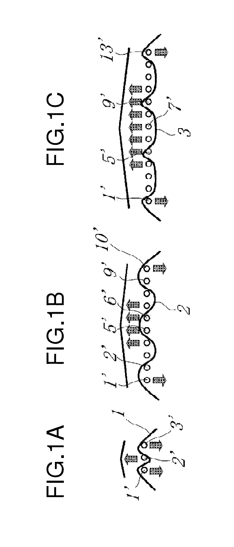
It is known that while an industrial two-layer fabric obtained by bringing together an upper side fabric and a lower side fabric with a binding yarn travels on a papermaking machine, there occurs abrasion at a position where the upper side fabric is brought into contact with the lower side fabric.
Particularly, with a recent increase in the speed of a papermaking machine, internal abrasion occurs more frequently.
The internal abrasion causes fluffing of the surface of the yarns inside the fabric and this deteriorates the airflow degree of the mesh, resulting in reduction in dehydration rate.
When the binding ratio is increased by the above-mentioned method, however, a dehydration mark is likely to appear in the upper side fabric.
As a result, paper made using such a fabric has on the surface thereof dehydration marks.
Uniform arrangement of convex sites as described above becomes a cause of not only dehydration marks but also a cause of deteriorating the surface smoothness of the fabric.
Decreasing a binding ratio, however, deteriorates the adhesion between an upper side fabric and a lower side fabric as described above and thereby causes internal abrasion.
There has been no design capable of satisfying all the required characteristics such as internal abrasion, dehydration mark, and surface smoothness.

Method used


Image

  • Industrial two-layer fabric
  • Industrial two-layer fabric
  • Industrial two-layer fabric

Examples


embodiment 1

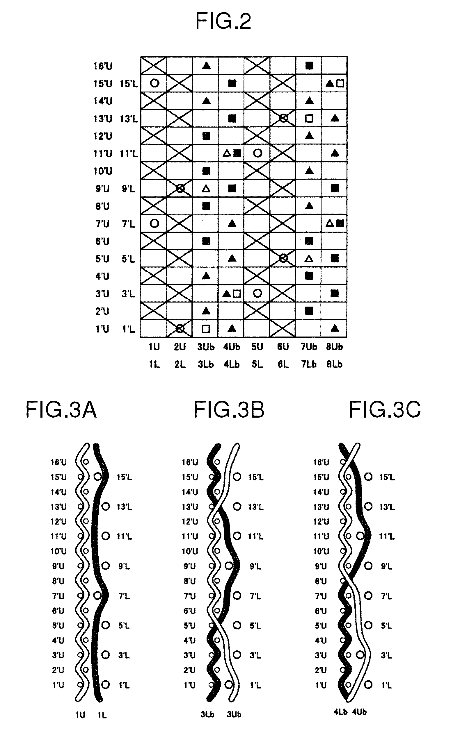
[0053]FIG. 2 is a design diagram showing a complete design or a repeating unit of Embodiment 1 according to the industrial two-layer fabric of the invention. The complete design has second warp pairs having no warp binding yarn and made of upper side warps (1U, 2U, 5U, and 6U) and lower side warps (1L, 2L, 5L, and 6L). Each of the upper side warps and each of the lower side warps of the second warp pairs having the same number are vertically arranged adjacent to each other and form the second warp pairs (1U, 1L), (2U, 2L), (5U, 5L) and (6U, 6L).

[0054]The complete design also has first warp pairs that consist of upper side warp binding yarns (3Ub, 4Ub, 7Ub, and 8Ub) and lower side warp binding yarns (3Lb, 4Lb, 7Lb, and 8Lb) each having a binding function. Each of the upper side warp binding yarns and each of the lower side warp binding yarns of the first warp pairs having the same number, are arranged adjacent to each other and form the first warp pairs (3Ub, 3Lb), (4Ub, 4Lb), (7Ub, ...

embodiment 2

[0064]FIG. 4 is a design diagram showing a complete design or a repeating unit of Embodiment 2 according to the industrial two-layer fabric of the invention. The complete design has second warp pairs having no warp binding yarn and made of upper side warps (1U, 2U, 5U, and 6U) and lower side warps (1L, 2L, 5L, and 6L) and first warp pairs made of upper side warp binding yarns (3Ub, 4Ub, 7Ub, and 8Ub) and lower side warp binding yarns (3Lb, 4Lb, 7Lb, and 8Lb) each having a binding function. In the first warp pairs shown in FIG. 4, two pairs, that is, a pair of 3Ub and 3Lb and a pair of 4Ub and 4Lb are adjacent to each other and two pairs, that is, a pair of 7Ub and 7Lb and a pair of 8Ub and 8Lb are adjacent to each other. Thus, the complete design has four first warp pairs. In the second warp pairs, two pairs, that is, a pair of 1U and 1L and a pair of 2U and 2L are adjacent to each other and two pairs, that is, a pair of 5U and 5L and a pair of 6U and 6L are adjacent to each other. ...

embodiment 3

[0076]FIG. 6 is a design diagram showing a complete design or a repeating unit of Embodiment 3 according to the industrial two-layer fabric of the invention. The complete design has second warp pairs having no warp binding yarn and made of upper side warps (1U, 2U, 5U, and 6U) and lower side warps (1L, 2L, 5L, and 6L) and first warp pairs made of upper side warp binding yarns (3Ub, 4Ub, 7Ub, and 8Ub) and lower side warp binding yarns (3Lb, 4Lb, 7Lb, and 8Lb) each having a binding function. In the first warp pairs, two pairs, that is, a pair of 3Ub and 3Lb and a pair of 4Ub and 4Lb are adjacent to each other and two pairs, that is, a pair of 7Ub and 7Lb and a pair of 8Ub and 8Lb are adjacent to each other. Thus, the complete design has four first warp pairs. In the second warp pairs, two pairs, that is, a pair of 1U and 1L and a pair of 2U and 2L are adjacent to each other and two pairs, that is, a pair of 5U and 5L and a pair of 6U and 6L are adjacent to each other. Thus, the comple...


PUM


Abstract

An industrial two-layer fabric of 16 or more shafts consists of an upper side fabric having upper side warps and upper side wefts and a lower side fabric having lower side warps and lower side wefts, the upper side fabric and the lower side fabric are bound by binding yarns. A first warp pair consists of a binding yarn and one of an adjacent upper side warp, an adjacent lower side warp and an adjacent binding yarn. A second warp pair consists of an upper side warp and an adjacent lower side warp. In a complete design, two or more of the first warp pairs are placed adjacent to each other, and two or more of the second warp pairs are placed adjacent to each other.

Description

BACKGROUND OF THE INVENTION[0001]1. Field of the Invention[0002]The present invention relates to an industrial two-layer fabric having a warp binding yarn, in particular, an industrial two-layer fabric featuring reduced internal abrasion, less dehydration marks, and excellent surface smoothness.[0003]2. Background Art[0004]Industrial fabrics obtained by weaving warps and wefts have conventionally been used widely. They have been used as, for example, papermaking fabrics, conveyor belts, and filter cloths and required to have fabric characteristics suited for intended uses or using environments, respectively. Of such fabrics, papermaking fabrics used in a papermaking step to dehydrate raw materials by making use of the screen of the fabrics should satisfy a severe demand. There is therefore a demand for the development of, for example, fabrics which are excellent in surface smoothness and therefore do not transfer a dehydration mark of the fabrics to paper; or fabrics having a dehydr...

Claims


Application Information

Patent Timeline
Patent Type & Authority Applications(United States)
IPC IPC(8): D03D11/00
CPCD03D11/00D21F1/0045
Inventor UEDA, IKUO
Owner NIPPON FILCON
Learn More